2 remote console – Reznor MAPS II Unit Installation Manual User Manual
Page 31
Form I-MAPS II, P/N 206131 (Rev 13), Page 31
Wire
Gauge
Maximum Sensor
Wire Length
(Digital Control)
AWG
Feet
Meters
14
800
244
16
500
152
18
310
94
20
200
61
22
124
38
Push the sensing element into the clip attached to the inside of the sensor holder. Turn
the metal holder so that the element will be shielded from direct airflow and will sense
the temperature in the airstream as it flows through the holes in the sensor holder.
At the location selected, mark the diamond-shaped hole required for the sensor holder.
Cut the hole no larger than required for the holder, approximately 1" x 1" (25mm x
25mm).
In the electrical box portion of the sensor holder, determine where the sensor wire
should come through the box and remove the knockout at that location.
3. Attach the sensor holder assembly. Slide the sensor holder into the opening in the
ductwork. Using four field-provided No. 6 sheetmetal screws, attach the box to the duc-
twork. Attach a field-supplied cable connector to the box, run the sensor wire out, and
attach the cover to the box.
4. Run the sensor wire to the unit. Digital control inputs are low-current, resistance-
based signals. The manufacturer recommends for optimum temperature control per-
formance that the analog and digital inputs (zone sensors, discharge air sensors, etc.)
that are connected to the FX05 or FX06 controller be routed to the unit in one of the
following manners:
• In separate field-supplied conduits, isolated from 24 VAC controls and line volt-
age power to the unit, OR
• If the digital wires are to be run in the same field-supplied conduit as the 24
VAC control wiring, the digital wiring must be completed using shielded cable
and bundled separately from 24 VAC control wiring. The shield must be drained
at the unit and taped on the opposite end.
NOTE: If wire is supplied
with the sensor, it is 22
AWG.
8.2 Remote Console
������
��
������
��
�
��������������
���
����
��
����
�������������
���� ����
����
�����
������
A selection of remote consoles is available with certain appropriate combi-
nations of controls factory mounted. All consoles include indicator lights for
blower and cooling operation and an auto/off control switch. NOTE: The auto/
off switch must be closed (Auto) for the display on the programmable control-
ler (
FIGURE 16, page 28) to read "on" (Terminals TB-48 and TB-49). Burner
indicator light, dirty filter light, and mode switches depend on option selection.
If the unit is ordered with a damper control option that includes a potentiometer,
the potentiometer may be mounted on the console.
If any of the field-mounted optional cooling/heating or reheat controls
are ordered, one may be mounted on the remote console. Console
dimensions with mounting ring are length 15-3/4" (400mm) x height
7-5/8" (194mm) x depth 2-5/8" (67mm). If recessing the console (not
using the mounting ring), subtract 7/8" (22mm) from the height and
width.
Wire controls on the remote console according to the wiring diagram.
Refer to the chart (left) for minimum control wire gauge by length.
Field Control Wiring Length/Gauge
Total Wire
Length
Distance from
Unit to Control
Minimum
Recommended
Wire Gauge
ft
M
ft
M
150 46
75
23
18
250 76
125
38
16
350 107 175
53
14
Dirty Filter Switch - If there is a dirty filter indicator light on the console, there
is a dirty filter switch in the unit. For location, see
FIGURE 20 or 21, page 33,
Item 14. After the unit is started, before continuous operation, the dirty filter
switch must be set.
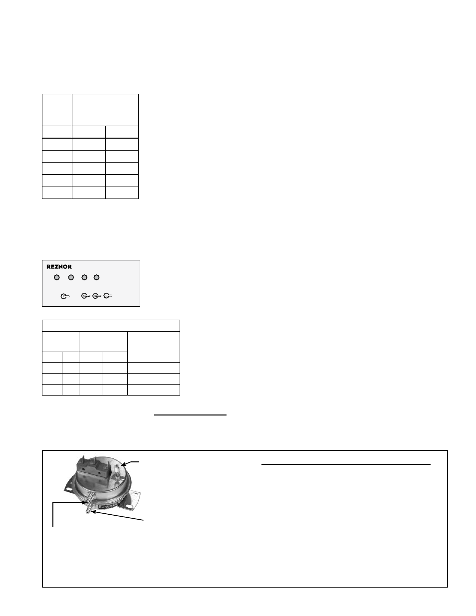
FIGURE 19 - Dirty
Filter Switch,
P/N 105507
Setscrew (on front of
switch) must be manually
adjusted after the system
is in operation.
Negative pressure
connection is toward
the "front or top" of
the switch (senses
blower side of filters)
Positive pressure
connection is toward the
"back or bottom" of the
switch (senses air inlet
side of filters)
Instructions for Setting Dirty Filter Switch -
With clean filters in place; all doors closed
(except electrical compartment); and the
blower operating, increase the pressure set-
ting by adjusting the setscrew on the switch
clockwise until the filter light is energized or the
screw is bottomed out. At that point, adjust the
setscrew three full turns counterclockwise or
until the screw is top-ended. At that setpoint,
the filter light will be activated at approximately
50% filter blockage.