3 gas heat module - models rdca and rdda (cont'd) – Reznor MAPS II Unit Installation Manual User Manual
Page 46
Form I-MAPS II, Page 46
Optional Gas
Pressure Safety
Switches
If the manifold is equipped with optional high and/or low gas pressure switches,
the switches protect against a malfunction that would cause an increase or
decrease in the regulated gas pressure.
The low gas pressure switch is an automatic reset switch factory set to activate
if the gas pressure is 50% of the minimum as stated on the unit rating plate.
The high gas pressure switch is a manually reset switch that is set to activate if
the gas pressure is 125% of the manifold pressure stated on the rating plate.
(See
FIGURES 33A
and
33B.)
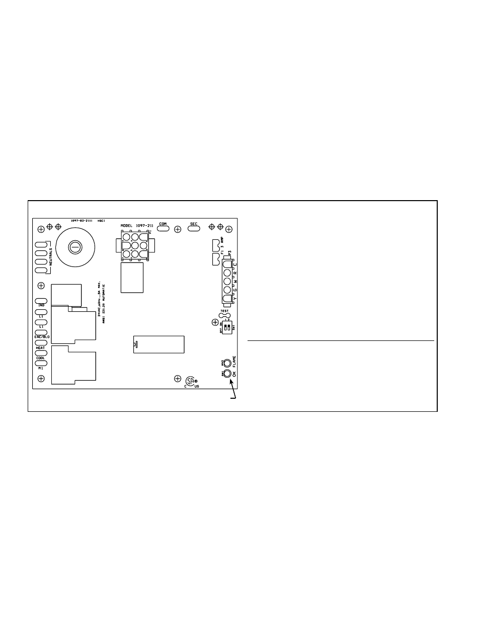
Control Status - Green LED Codes
Steady ON . Normal Operation, No call for heat
Fast Flash .. Normal Operation, Call for heat
1 Flash ....... System Lockout, Failed to detect or
sustain flame
2 Flashes ... Pressure switch did not close within
30 seconds of venter motor
3 Flashes ... High limit switch open
4 Flashes ... Pressure switch is closed before
venter motor is energized
Steady OFF Blown Fuse, No Power, or
Defective Board
Flame Status - Yellow LED Codes
Steady ON . Flame is sensed
Slow Flash . Weak flame (current below 1.0
microamps ±50%)
Fast Flash .. Undesired Flame (valve open and
no call for heat)
FIGURE 387 – DSI Integrated Control Module (circuit board)
�����
�����������
�������
����
����
����������
�����������
������
������
�
LED Lights
9.3.3 Ignition System
This furnace is equipped with a direct spark integrated control module (circuit
board). The module monitors the safety devices and controls the operation of
the venter motors and the gas valve between heat cycles.
1) Call for Heat - The heating/cooling system controller calls for heat. The igni-
tion system circuit board checks to see that the limit switch is closed and the
pressure switch is open. If the limit switch is open, the circuit board responds
as defined in the “Abnormal Heat Cycle, Limit Switch Operation”. If the pres-
sure switch is closed, the circuit board will do four flashes on the green LED
and wait indefinitely for the pressure switch to open. If the pressure switch is
open, the circuit board proceeds to prepurge.
2) Prepurge - The circuit board energizes the venter motor and waits for the
pressure switch to close. If the pressure switch does not close within 30 sec-
onds of the venter motor energizing, the circuit board will do two flashes on the
green LED. The circuit board will leave the venter motor energized indefinitely
as long as the call for heat remains and the pressure switch is open.
When the pressure switch is proven closed, the circuit board begins the pre-
purge time. If flame is present any time while in prepurge, the prepurge time
is restarted. If flame is present long enough to cause lockout, the circuit board
responds as defined in “Fault Modes, Undesired Flame”.
Normal Heat Cycle
Operating Sequence
9.3 Gas Heat Module - Models RDCA and RDDA (cont'd)
9. Optional
Equipment
including
Heat Sections
(cont'd)
9.3.2 Gas Heat Module - Mechanical (cont'd)
9.3.2.1 Gas Piping and Pressures (cont'd)