Reznor MAPS II Unit Installation Manual User Manual
Page 36
Form I-MAPS II, Page 36
ing, the pressure null switch activates the damper motor driving the outside air
damper towards the full open position and the recirculated air damper towards
the closed position. Conversely, as less pressure is required, the switch drives
the dampers in the opposite direction.
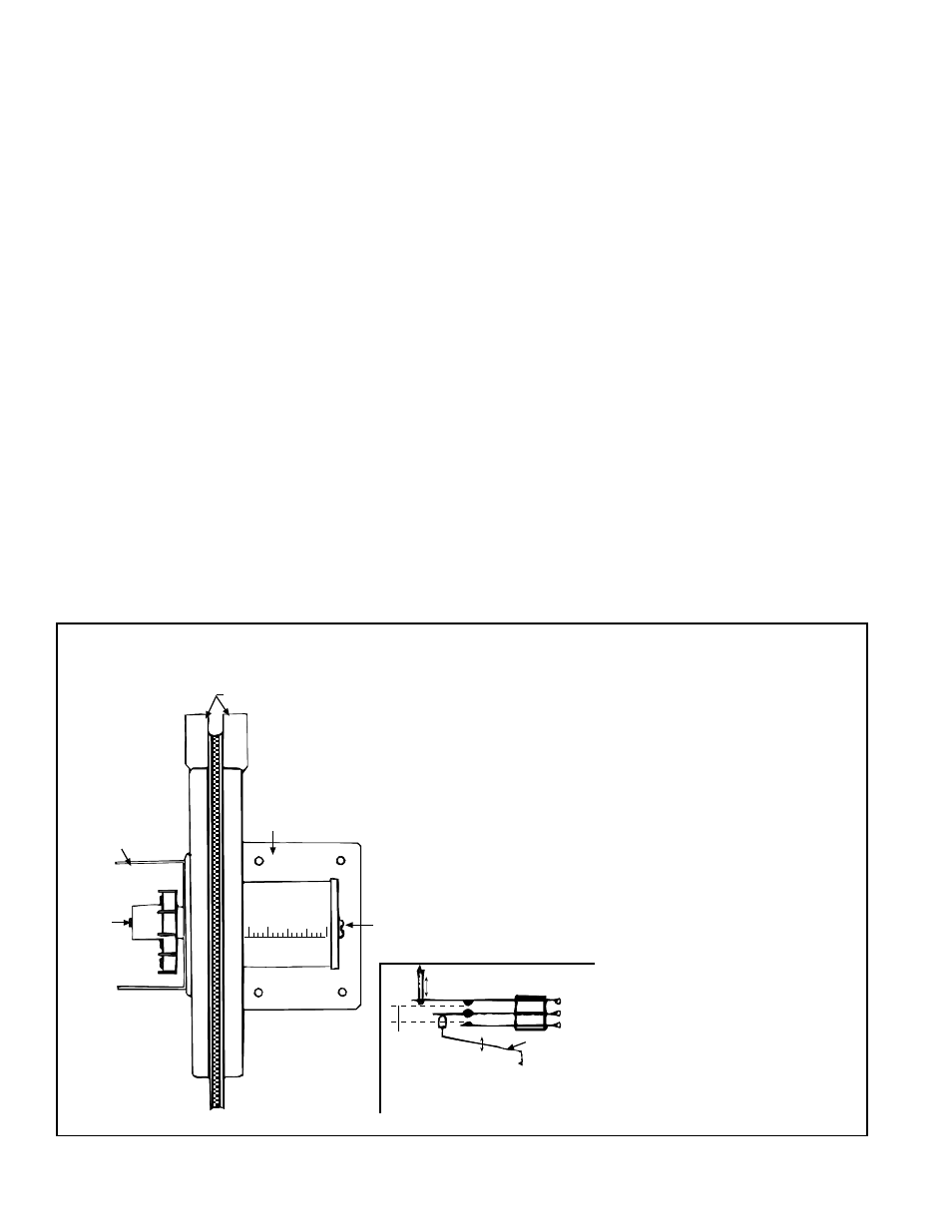
Installation Instructions for Pressure Null Switch
1. Select an indoor location free from excessive vibration where oil or water
will not drip onto the switch and where ambient temperature will be within a
range of -30°F (dry air) to 110°F.
2. Mount the switch with the diaphragm in a vertical plane. The switch is
position sensitive and is calibrated to operate properly when the diaphragm
is vertical. Mount switch securely.
3. Connect the pressure taps on the top of the switch to sources of air pres-
sure differential. Metal tubing with 1/4" O.D. is recommended, but any tub-
ing system which will not unduly restrict the air flow may be used. To main-
tain a positive building pressure, vent the low pressure tap to the outdoors
and allow the high pressure tap to monitor building pressure. To maintain a
negative building pressure, reverse the functions of the high and low pres-
sure taps. In either case, be sure that the outdoor vent is protected from
the wind and screened from insects.
4. Adjustment of the Switch - The "HIGH" actuation point of the null switch
is indicated on a calibrated scale secured to the transparent range screw
enclosure. Building pressure is set by turning the adjustment screw. The
"Low" actuation point is set by adjusting the span of the null by turning the
span adjustment screw. The span range is .01 to .03" w.c.
5. See the wiring diagram included with the furnace to make electrical con-
nections.
������������
����
������
�����
��������������
�������������
���
����
��������
������������
����������
����������
����������
���������
���
������
����
���������������
�������
��������
�������
��������������������������������������������
FIGURE 28 - Pressure Null Switch (shipped separately for use with Options AR23 and
AR27)
9. Optional
Equipment
including
Heat Sections
(cont'd)
9.1.1 Inlet Air Options
- Dampers and
Damper Controls
(cont'd)
IMPORTANT: To eliminate shipping damage to the switch
contacts, the manufacturer reduced the span adjustment to
zero before shipping. The span should be adjusted prior to
using the switch. (If the switch has been installed, disconnect
the vent tube so that the null switch is in a neutral position.)
Remove the electrical box cover and while observing the
contacts, turn the span adjustment screw slowly in a clock-
wise direction. Continue turning the adjustment screw until
you are able to see gaps between the common and both the
low and high contacts. A minimum gap provides the greatest
sensitivity. The wider the gap the lower the sensitivity.
9.1 Inlet Air Control
and Energy
Recovery Options
(cont'd)