Reznor MAPS II Unit Installation Manual User Manual
Page 48
Form I-MAPS II, Page 48
Ignition System
Fault Modes
sure switch recognition delay, the circuit board will respond to the loss of flame.
If the pressure switch remains open for 2 seconds and the flame remains, the
circuit board de-energizes the gas valve and the venter motor runs through
postpurge
Undesired Flame - If flame is sensed longer than 20 seconds while the gas
valve is de-energized, the circuit board shall energize the venter motor. When
flame is no longer sensed, the venter motor will run through postpurge. The
circuit board will do a soft lockout, but will still respond to open limit and flame.
The FLAME (yellow) LED shall flash rapidly when lockout is due to undesired
flame.
Gas Valve Relay Fault - If the circuit board senses the gas valve as energized
for more than one second when the circuit board is not attempting to energize
the gas valve, or the gas valve is sensed as not energized when it is supposed
to be energized, then the circuit board will lockout with the green LED off. The
control assumes either the contacts of the relay driving the gas valve have
welded shut, or the sensing circuit has failed. The venter motor is forced off to
open the pressure switch to stop gas flow unless flame is present.
If the gas valve was sensed as closed when it should be open, and has not de-
energized after the venter motor was shutoff for 15 seconds, then the venter
motor is re-energized to vent the unburned gas.
Soft Lockout - The circuit board shall not initiate a call for heat while in lock-
out. The circuit board will still respond to an open limit and undesired flame.
Lockout shall automatically reset after one hour. Lockout may be manually
reset by removing power from the circuit board for more than one second or
removing the call for heat for more than one and less than 20 seconds.
Hard Lockout - If the circuit board detects a fault on the board, the status LED
will be de-energized, and the circuit board will lockout as long as the fault
remains. A hard lockout will automatically reset if the hardware fault clears.
Power Interruption - During a momentary power interruption or at voltage
levels below the minimum operating voltage (line voltage or low voltage) the
ignition system will self-recover without lockout when voltage returns to the
operating range.
Power interruptions of less than 80mS shall not cause the circuit board to
change operating states. Power interruptions greater than 80mS may cause
the circuit board to interrupt the current operating cycle and re-start.
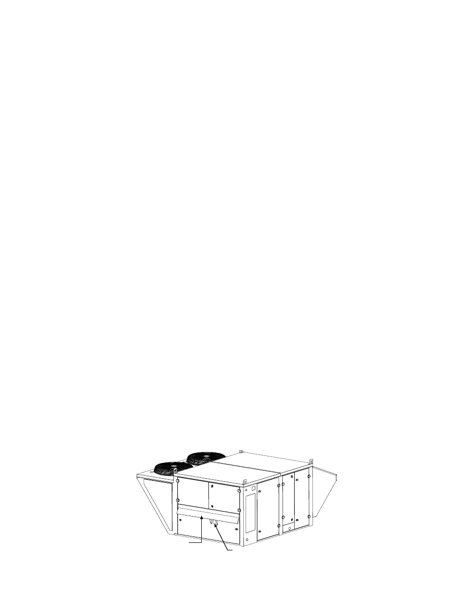
9.3.4 Venting and
Combustion Air
Location of the Vent
and Combustion Air
Inlets
FIGURE 39 -
Location of Flue
Exhaust (vent) and
Combustion Air
Openings
��������
�����������
������
��������������
��������������������
�������������������
��������������������
The gas heat section is power
vented. Presence of
combustion air pres-
sure is monitored by a
combustion air proving
switch.
The combustion air and flue
gas openings are carefully
designed screened openings
located on the side of the unit.
Position the system so that the flue dis-
charge is not directed at any fresh air
inlet.
9.3 Gas Heat Module - Models RDCA and RDDA (cont'd)
9. Optional
Equipment
including
Heat Sections
(cont'd)
9.3.3 Ignition System (cont'd)
Abnormal Heat Cycle Functions (cont'd)