5 startup form, Startup form, Startup checklist - general checks (reference) – Reznor MAPS II Unit Installation Manual User Manual
Page 57
Form I-MAPS II, P/N 206131 (Rev 13), Page 57
Applies to:
MAPS II Model Series RCA, RDA, RDCA, RDDA, RECA, and REDA
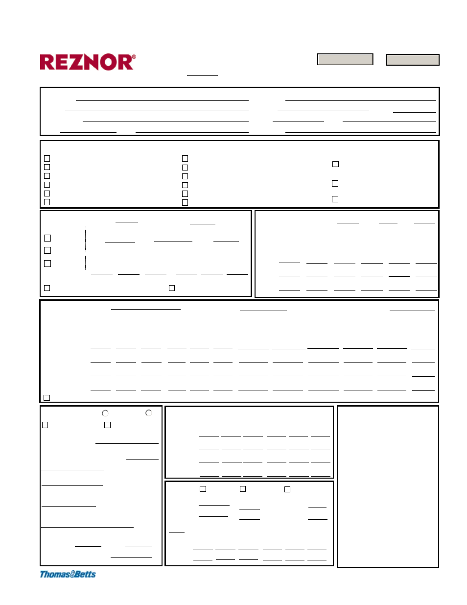
Modular Air Processing Systems
STARTUP FORM
Job Name
Contractor
Verify shipping brackets are removed.
Inspect unit for damage. (I-MAPS II, Sec. 3.1)
Inspect dampers.
Check condensate connections. (I-MAPS II, Sec. 6.2)
Verify air filters are installed. (O-MAPS II, Sec. 3)
Verify all copper tubing is isolated and does not rub.
Check for manual resets (firestat, high
gas pressure switch)
Check outside air hood and filters. (I-MAPS II, Sec. 6.3)
Check and tighten all electrical terminals.
Check clearances (I-MAPS II, Sec. 4.3)
Blower
Assembly
Alignment
Belt tension
Rotation
Motor HP
Seal electrical entrances.
Nameplate Amps
RPM
E.S.P.
L1 - L2
L2 - L3
L3 - L1
RLA-1
RLA-2
RLA-3
Startup Checklist - General Checks (Reference)
Condenser
Fans
Nameplate HP
Volts
RLA
Fan 1
Fan 2
Fan 3
L2 - L3
L3 - L1
RLA-1
RLA-2
RLA-3
Compressor
Data
Outdoor Air Conditions:
Entering Dry Bulb
Entering Wet Bulb, Dewpoint, or % RH
Circuit
Compressor A
Compressor B
Compressor C
D or Reheat DH
RLA-3
RLA-2
RLA-1
L3 - L1
L2 - L3
L1 - L2
Nameplate
RLA
Head Press
PSIG
Suct Press
PSIG
Superheat
DAT
Subcooling
Street
City, ST, Zip
Date
Contact
Model
Serial No.
Gas Heat Section
Leak test gas piping
Purge air from lines
Inlet Gas Pressure
Maximum Inlet Gas Pressure: 14" for both natural
gas & LP
Operational Inlet Gas Pressure
Minimum Inlet Gas Pressure: 5.5"w.c. for 3-stage
naturalgas (AG55); 6.0"w.c. for 6:1 modulation
natural gas (AG57);11"w.c. for 3-stage LP (AG55)
Check Manifold Pressure (Desired outlet pressure
of single stage valve from 0-2000 ft ( 0-610M) at full
fire is 3.5" w.c. for natural gas or 10" w.c. for LP.
Operational Manifold Gas Pressure:
1/3 or Single
Burner
2/3
Burner
Electric
Heat
Section
Voltage
Option
ERV
Exhaust
Assy
Alignment
Belt tension
Air balance
L1 - L2 L2 - L3 L3 - L1 RLA-1 RLA-2 RLA-3
Intake Motor HP
Nameplate Amps
Nameplate Amps
Exhaust Mtr HP
Motor
Intake
Exhaust
Comments
Natural Gas
LP
Full Burner (Sizes 450-700)
L1 - L2
Check discharge and space sensors.
Check all fans for free movement.
Check for voltage imbalance.
(I-MAPS II, Sec. 7.2)
Tighten all screws on pulleys, bearings, and
fans (I-MAPS II, Sec. 6.4; O-MAPS II, Sec 4)
Check optional dirty filter
switch. (I-MAPS II, Sec. 8.2)
Check optional hot gas bypass valve. (I-MAPS II, Sec. 7.7)
Phone
Size
Tag
Check fuses/breakers for correct
sizing (Check unit rating plate for
electrical requirements.)
CFM.
Voltage
Amperage
Amperage
Voltage
Amperage
Voltage
Voltage
Amperage
Amperage
L3 - L1
L2 - L3
L1 - L2
RLA-3
RLA-2
RLA-1
1
2
3
4
©2008 Thomas & Betts Corporation; All rights reserved; Form ST-MAPS II, P/N 257072
Print Form
Reset Form
10.5 Startup Form
(To fill out this form on line and print or to print a blank copy, go to www.RezSpec.
com.)