Warning: pressure testing supply piping, 3 gas heat module - models rdca and rdda (cont'd), Figure 32 - gas connection – Reznor MAPS II Unit Installation Manual User Manual
Page 40: Gas connection size, Sizing gas supply lines
Form I-MAPS II, Page 40
WARNING: PRESSURE TESTING SUPPLY PIPING
Test pressures ABOVE 1/2 psi (3.5kPa): Disconnect the heater and the
manual valve from the gas supply line which is to be tested. Cap or plug the
supply line.
Test pressure EQUAL TO or BELOW 1/2 psi (3.5kPa): Before testing, close
the manual valve at the heater.
Furnaces for natural gas are orificed for operating with gas having a heating
value of 1000 (±50) BTU per cubic ft. If the gas at the installation does not meet
this specification, consult the factory for proper orifice.
Pipe joint compounds (pipe dope) shall be resistant to the action of liquefied
petroleum gas or any other chemical constituents of the gas being supplied.
WARNING: All components of a gas supply system must be
leak tested prior to placing equipment in service. NEVER
TEST FOR LEAKS WITH AN OPEN FLAME. Failure to comply
could result in personal injury, property damage or death.
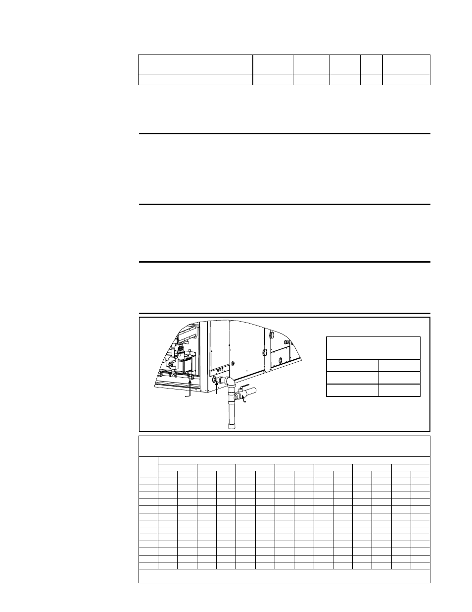
FIGURE 32 - Gas
Connection
���������
����������
����
���
������
�������
������
������
����
Gas Connection Size
Heat Section Gas
Connection
100 - 300
1/2"
350 - 400
3/4"
450 - 700
1"
Sizing Gas Supply
Lines
CAPACITY OF PIPING - Cubic Feet per Hour based on 0.3" w.c. Pressure Drop
Specific Gravity for Natural Gas -- 0.6 (Natural Gas -- 1000 BTU/Cubic Ft)
Specific Gravity for Propane Gas -- 1.6 (Propane Gas -- 2550 BTU/Cubic Ft)
Length
Diameter of Pipe
of
1/2"
3/4"
1"
1-1/4"
1-1/2"
2"
2-1/2"
Pipe
Natural Propane Natural Propane Natural Propane Natural Propane Natural Propane Natural Propane Natural Propane
20 ft
92
56
190
116
350
214
730
445
1100
671
2100
1281
3300
2013
30 ft
73
45
152
93
285
174
590
360
890
543
1650
1007
2700
1647
40 ft
63
38
130
79
245
149
500
305
760
464
1450
885
2300
1403
50 ft
56
34
115
70
215
131
440
268
670
409
1270
775
2000
1220
60 ft
50
31
105
64
195
119
400
244
610
372
1105
674
1850
1129
70 ft
46
28
96
59
180
110
370
226
560
342
1050
641
1700
1037
80 ft
43
26
90
55
170
104
350
214
530
323
990
604
1600
976
90 ft
40
24
84
51
160
98
320
195
490
299
930
567
1500
915
100 ft
38
23
79
48
150
92
305
186
460
281
870
531
1400
854
125 ft
34
21
72
44
130
79
275
168
410
250
780
476
1250
763
150 ft
31
19
64
39
120
73
250
153
380
232
710
433
1130
689
175 ft
28
17
59
36
110
67
225
137
350
214
650
397
1050
641
200 ft
26
16
55
34
100
61
210
128
320
195
610
372
980
598
Note: When sizing supply lines, consider possibilities of future expansion and increased requirements.
Refer to National Fuel Gas Code for additional information on line sizing.
Temperature
Guidelines for Gas
Heat Section
All piping must be in accordance with requirements outlined in the National Fuel
Gas Code ANSI/Z223.1a (latest edition) or CSA-B149.1 and B149.2. Gas sup-
ply piping installation should conform with good practice and with local codes.
9.3.2 Gas Heat
Module - Mechanical
9.3.2.1 Gas Piping and Pressures
Minimum Circulating Discharge
Air Temperature (°F)
80
75
70
65
60
Minimum Design Ambient (°F)
-30 to - 21 -20 to - 11 -10 to -1 0 to 9 10 and above
9. Optional Equipment including Heat Sections (cont'd)
9.3 Gas Heat Module - Models RDCA and RDDA (cont'd)
NOTE: If a Model
JHUP-0250 duct
furnace curb
section is part of the
installation, much of
the information in this
section applies to the
duct furnace also;
see Paragraph 9.4.