3 disconnect switch, 4 control wiring, 3 disconnect switch 7.4 control wiring – Reznor MAPS II Unit Installation Manual User Manual
Page 25
Form I-MAPS II, P/N 206131 (Rev 13), Page 25
Voltage
The electric supply to the unit must meet stringent requirements for the system
to operate properly. Voltage supply and voltage imbalance between phases
should be within the tolerances listed below. If the power is not within these
voltage tolerances, contact the power company prior to operating the system.
Voltage Supply - See voltage use range on the rating plate. Measure (and
record) each supply leg voltage at all line disconnect switches. Readings must
fall within the allowable range on the rating plate.
Voltage Imbalance - In a 3-phase system, excessive voltage imbalance
between phases will cause motors to overheat and eventually fail. Maximum
allowable imbalance is 2%. To determine voltage imbalance, use recorded
voltage measurements in this formula.
NOTE: If the system
was ordered with a volt-
age loss safety switch
(Option BF14,
FIGURE
16B) that monitors volt-
age balance, the circuit
to the compressors will
be opened in the event of
voltage imbalance. In six
minutes, the switch will
recheck the circuit. If the
problem is eliminated, the
circuit will be re-activated.
Key: V1, V2, V3 = line voltages as measured Formula:
VA (average) =
(V1 + V2 + V3)
3
% Voltage Imbalance = [100 x (VA - VD)]
VA
VD = Line voltage (V1, V2, or V3) that
deviates farthest from average
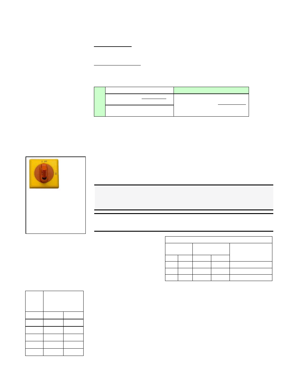
7.3 Disconnect
Switch
FIGURE 13 - Built-in,
non-fusible, lockable
Disconnect Switch
NOTE: Illustration
shows disconnect used
for cooling only and
cooling with a gas heat
section. Cooling with
electric heat requires a
larger disconnect.
The system is equipped with a built-in non-fusible, lockable disconnect switch
(
FIGURE 13). If an additional optional fusible disconnect is ordered, it will be
shipped separately for field installation (or may be field supplied).
When running electrical conduit, be careful that it is clear of all access panels.
The built-in disconnect switch requires copper wiring with ampacity based on
60°C maximum temperature rating at the line side terminals.
If field installing an additional disconnect switch, it is recommended that there
is at least four feet (1.2M) of service room between the switch and system
access panels. When providing or replacing fuses in a fusible disconnect, use
dual element time delay fuses and size according to the rating plate.
DANGER: To prevent injury or death due to electrocution or
contact with moving parts, lock disconnect switch open. See
Hazard Levels, page 2.
WARNING: If an optional gas furnace is included, if you turn
off the power supply, turn off the gas.
7.4 Control Wiring
Field Control Wiring Length/Gauge
Total Wire
Length
Distance from Unit
to Control
Minimum
Recommended Wire
Gauge
ft
M
ft
M
150
46
75
23
18
250
76
125
38
16
350
107
175
53
14
Wire 24 volt controls accord-
ing to the wiring diagram.
Refer to the chart on the
right for minimum control
wire gauge by length.
Digital control inputs are low-current, resistance-based signals. The manu-
facturer recommends for optimum temperature control performance that the
analog and digital inputs (zone sensors, discharge air sensors, etc.) that are
connected to the FX05 or FX06 controller be routed in one of the following
manners:
• In separate conduits, isolated from 24VAC controls and line voltage power
to the unit; OR
• If the wires are to be run in the same conduit as the 24 VAC control wir-
ing, the sensor wiring must use shielded cable and be bundled separately
from 24 VAC control wiring. The shield must be drained at the unit and
taped on the opposite end.
Digital Control Wiring
Wire
Gauge
Maximum Sensor
Wire Length
(Digital Control)
AWG
Feet
Meters
14
800
244
16
500
152
18
310
94
20
200
61
22
124
38
NOTE: If wire is included with the digital sensor, it is 22 AWG.