4 miscellaneous electrical and control options, 4 miscellaneous electrical / control options – Reznor MAPS II Unit Installation Manual User Manual
Page 33
Form I-MAPS II, P/N 206131 (Rev 13), Page 33
TUBING SECTION
• Low Refrigerant Pressure Cutouts
• High Refrigerant Pressure Cutouts
• Filter Driers
• Liquid Line Service Gauge Ports
COMPRESSOR SECTION
• Ckt A Compressor
• Ckt B Compressor
• Ckt C Compressor
• Discharge & Suction Service Ports
• Optional Hot Gas Bypass Valve(s)
HIGH VOLTAGE ELECTRICAL
COMPARTMENT
1) Blower Motor Contactor or Starter
2) Control Transformers (as required)
3) Dehumidification Compressor
Contactor (RDA,RDDA,REDA)
4) Condenser/Compressor Contactor
5) Optional Phase Loss/Phase Rever-
sal Control (optional beginning
10/05; standard prior to 10/05)
6) Optional Damper Motor
Transformer
7) Optional Over/Under Voltage
Control
8A&B) Condenser Motor Capacitors
9) Optional Convenience Outlet
(requires separate supply line)
• Outside Air Relative Humidity
Transmitter (Std RDA/
RDDA/REDA; Optional
RCA/RDCA/RECA)
• Ckt D or Dh Compressor
• Optional Damper Motor
Models RDCA & RDDA With Gas
Heat Section (FIGURE 20 only):
21) Venter Assembly
22) Single-Stage Gas Valves
23) Optional Modulating Gas Valve
24) Optional Low Gas pressure
Switch
25) Optional High Gas Pressure
Switch
Models RECA & REDA With
Electric Heat Section (FIGURE
21 only):
26) Fuse Block/Fuses
27) Contactor
28) Low Voltage Terminals
29) Manual Reset Limit
30) Auto Reset Limit
FIELD INSTALLED
• Discharge Air Sensor (supply duct)
• Optional Return Air Firestat (duct)
• Optional Discharge Air Firestat
(duct)
• Optional Smoke Detector (duct)
• Optional wall-mounted controls in
Paragraph 8.1
AUXILIARY COMPARTMENT
10) Digital Controller (FX05 or FX06)
11) Air Proving Pressure Switch
12&13) Optional Control Relays
14) Optional Dirty Filter Switch
15) Optional Time Clock or BAS Card
16) Humidity Input Converter
Models RDCA & RDDA With Gas
Heat Section (FIGURE 20 only):
17) Combustion Air Pressure Switch
18) Ignition Control
19) Optional Power Signal Converter
20) Venter Motor Capacitor (line
voltage)
BLOWER SECTION
• Blower Motor
Models RDCA & RDDA With Gas
Heat Section (FIGURE 20 only):
• Limit Control (capillary type)
COIL SECTION
• Evaporator Coils
• Thermal Expansion Valves
• Froststat (one per cooling circuit)
• Optional Subcooling Valves
(RCA/RDCA/RECA)
FILTER AND INLET AIR
SECTION
• Inlet Air, Humidity, & Override
Sensors
8.4 Miscellaneous
Electrical and
Control Options
Other electrical or control options that could have been ordered with the unit
include phase loss monitor, over or under voltage protection, exhaust fan relay,
photoelectric air duct smoke detector, an inlet or discharge firestat, or a 115V
convenience outlet. See
FIGURES 22-26 to identify each control and its option
code. Consult the system wiring diagram for option identification. For location
of unit-mounted controls, see
FIGURE 20 or 21.
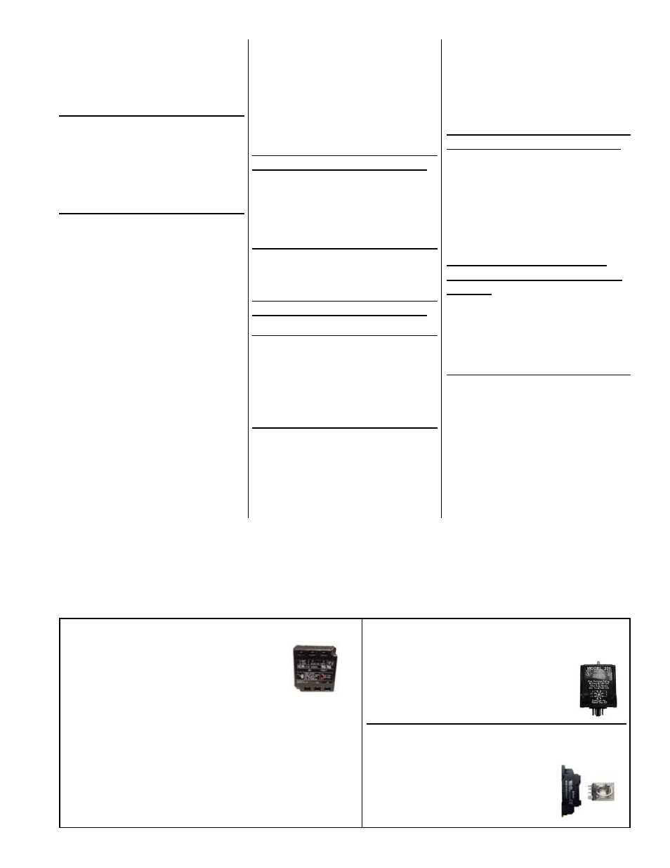
FIGURE 22B - Opt BF14, Over/Under
Voltage Protection, P/N 176826
(factory installed)
Shuts unit down on high or low volt-
age condition. Resets automatically
when power condition is corrected.
FIGURE 23 - Option BG3, Exhaust Fan
Relay, P/N 211411 (factory installed)
DPDT relay for coordination with
operation of building exhaust fan
Socket is
P/N 211415..
Auto Reset
Phase Loss
Device
With a phase loss monitor the cool-
ing compressors or heat sections
will not start or will shutdown if a
phase loss or phase reversal situa-
tion is present. This is an auto reset
device. If needed, interchange two
FIGURE 22A - Opt BF15, Phase Loss Monitor,
P/N 206105 (factory installed)
wires on the 3-phase supply connections to the line
side of the disconnect switch. DO NOT change load
side wiring. All factory installed wiring is color-coded
matched to assist in making certain the phase integrity
is in tact and to assist in troubleshooting if necessary.