Reznor MAPS II Unit Installation Manual User Manual
Page 43
Form I-MAPS II, P/N 206131 (Rev 13), Page 43
Instructions for
Checking Outlet
Pressure of Valves
(can only be done
after heater is
operating)
WARNING: Mani-
fold gas pressure
must never exceed
3.5" w.c. for natural
gas or 10" w.c. for
propane gas.
Manifold Pressure
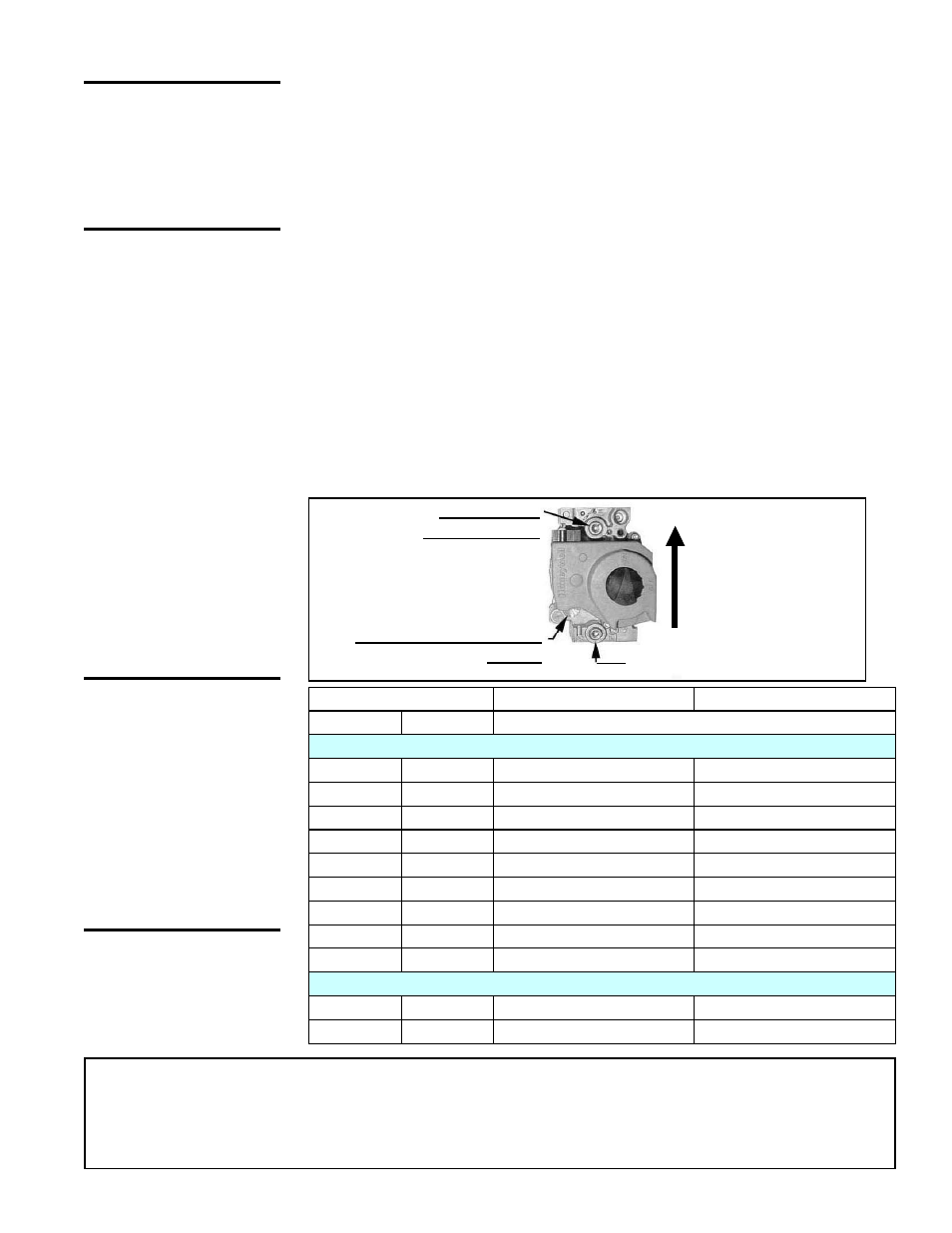
FIGURE 36 - View
of Standard Single-
Stage Valve (all units
have two) showing
Outlet Pressure Tap
and Adjustment
Locations
1/8” Output
Pressure Tap
Inlet Pressure Tap
Pressure Adjustment
Screw
Altitude
Natural Gas
Propane
Feet
Meters
Outlet Pressure of Single Stage Valves at FULL RATE
Manifold Pressure Settings by Altitude for the UNITED STATES
0-2000
0-610
3.5" w.c.
10.0" w.c.
2001-3000
611-915
3.1" w.c.
8.8" w.c.
3001-4000
916-1220
3.0" w.c.
8.5" w.c.
4001-5000
1221-1525
2.8" w.c.
8.1" w.c.
5001-6000
1526-1830
2.7" w.c.
7.7" w.c.
6001-7000
1831-2135
2.6" w.c.
7.4" w.c.
7001-8000
2136-2440
2.5" w.c.
7.1" w.c.
8001-9000
2441-2745
2.4" w.c.
6.7" w.c.
9001-10000 2746-3045
2.3" w.c.
6.7" w.c.
Manifold Pressure Settings by Altitude for CANADA
0-2000
0-610
3.5" w.c.
10.0" w.c.
2001-4500
611-1373
2.8" w.c.
8.1" w.c.
The valves are set at the factory for the appropriate outlet pressure. Check the
furnace rating plate for the manifold pressure setting.
Measuring manifold gas pressure cannot be done until the heater is in opera-
tion. It is included in the steps of the "Check-Test-Start" procedure in Para-
graph 10. The following warnings and instructions apply.
All furnaces haves two or three single-stage gas valves. Follow the instructions
to check the outlet pressure of all valves. If equipped with an optional modulat-
ing/regulating valve, unit must be operating at full rate.
Measure the Full Fire Outlet Pressure of all Single-Stage Valves - Turn the
manual valve in the gas line off. Locate the 1/8” output pressure tap on the first
single-stage gas valve (See
FIGURE 36). Connect a manometer to the 1/8"
pipe outlet pressure tap in the valve.
NOTE: A manometer (fluid-filled gauge) is
recommended rather than a spring type gauge due to the difficulty of maintain-
ing calibration of a spring type gauge.
Turn on the manual gas valve. Check the outlet pressure. (Reminder: If the
unit has optional 6:1 modulating turndown, burner must be at full fire.) Manifold
pressure for sea level operation should be 3.5" w.c. for natural gas or 10.0" w.c.
for propane gas. If the unit was ordered for high altitude operation, check the
high altitude plate or the Table below.
In most cases the outlet pressure will be correct, but in the rare instance that
adjustment is required, refer to
FIGURE 36 and follow the instructions.
Adjustment to the valve outlet pressure setting is rarely necessary. If adjustment is necessary, remove the
cap from the adjustment screw. Set pressure to correct setting by turning the regulator screw IN (clock-
wise) to increase pressure. Turn regulator screw OUT (counterclockwise) to decrease pressure. After an
adjustment is made, cycle the burner. Re-check the outlet pressure. When outlet pressure is correct for the
installation, remove the manometer and replace the cap. Check for leak at the pressure tap fitting.
CAUTION: DO NOT
bottom out the gas
valve regulator
adjusting screw.
This can result
in unregulated
manifold pressure
causing excess
overfire and heat
exchanger failure.