5 electric heat section - model reca and, Model reda, Top view – Reznor MAPS II Unit Installation Manual User Manual
Page 51: Electric heat capacity and sequence of operation
Form I-MAPS II, P/N 206131 (Rev 13), Page 51
9.5 Electric Heat
Section - Model
RECA and Model
REDA
A system with an electric heat section is equipped to provide from 5 to 88 kw
of electric heat. Depending on the size, electric heat sections provide one or
three stages of heating operation. Call for heat and staging occur in response
to system controls (See Paragraph 8).
Electric Heat Capacity and Sequence of Operation
NOTE: 575V and 600V apply to Model RECA only.
Electric Heat Capacity Table
Size
240/480/600V
208V
230/460/575V
KW
MBH
KW
MBH
KW
MBH
05S
5
17.1
3.8
12.8
4.6
15.7
10S
10
34.1
7.5
25.6
9.2
31.4
15S
15
51.2
11.3
38.4
13.8
47.1
20S
20
68.3
15.0
51.2
18.4
62.8
24S
24
82.0
18.0
61.5
22.1
75.4
15
15
51.2
11.3
38.4
13.8
47.1
20
20
68.3
15.0
51.2
18.4
62.8
25
25
85.4
18.8
64.0
23.0
78.5
30
30
102.5
22.5
76.8
27.6
94.3
35
35
119.5
26.3
89.6
32.2
110.0
39
39
133.2
29.3
99.9
35.9
122.5
60
60
204.9
45.0
153.7
55.2
188.5
75
75
256.1
56.3
192.1
69.0
235.6
88
88
300.5
66.0
225.4
81.0
276.5
Size
(kW)
Size
Cabinet
Electric Heaters Sequence of Operation
Stage 1
Stage 2
Stage 3
5
05S
A
5
-
-
10
10S
A
10
-
-
15
15S
A
15
-
-
20
20S
A
20
-
-
24
24S
A
24
-
-
15
15
A or B
5
10
5 + 10
20
20
A or B
5
15
5 + 15
25
25
A or B
10
15
10 + 15
30
30
A or B
10
20
10 + 20
35
35
A or B
15
20
15 + 20
39
39
A, B, or C
15
24
15 + 24
50
50
B or C
15
15+15
15+15+10+10
60
60
B or C
10+10
20+20
10+10+20+20
75
75
B or C
20
20+15+20
20+15+20+20
88
88
B or C
24
20+24+20
20+24+20+24
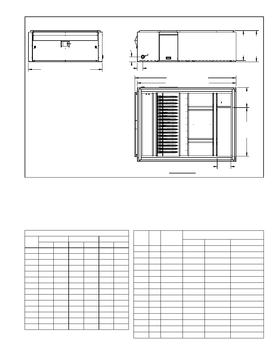
FIGURE 40B - Dimensions of a Model JHUP-0250 Duct Furnace Curb Section
Duct Furnace
Burner Access Door
Limit
Control
Door
57-1/16” (1449mm)
4-1/4” (108mm)
3-27/32”
(98mm)
76-1/4” (1937mm)
78-3/16” (1981mm)
15-1/2”
(394mm)
37-1/2”
(953mm)
23-1/8” (587mm)
24-3/32” (612mm)
10-17/32”
(267mm)
Gas
Supply
Entrance
Flue Outlet
Combustion Air Inlet
Top View
See Paragraph 5.3
for instructions on
mounting the duct
furnace curb section
on the roof curb.