Controls (cont'd), 1 digital control systems (cont'd) – Reznor MAPS II Unit Installation Manual User Manual
Page 30
Form I-MAPS II, Page 30
FIGURE 17 - Dis-
charge Air Sensor
Assembly in heating
systems (RDCA/
RDDA/RECA/REDA)
or cooling only sys-
tems with Option DU1
8. Controls (cont'd)
8.1 Digital Control
Systems (cont'd)
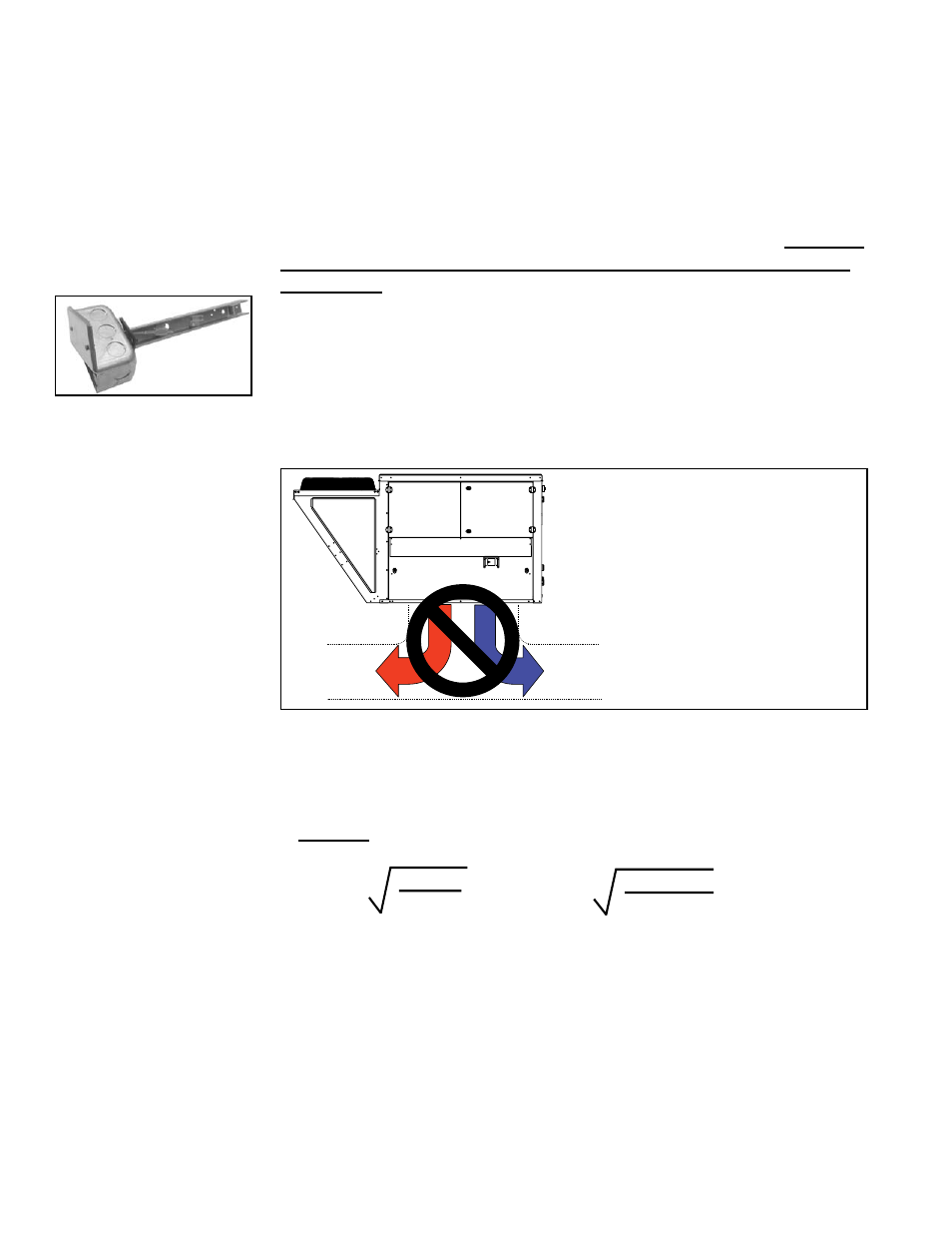
If the unit is installed in a system with
immediate “T” configuration leaving
the discharge, the 1/3 – 2/3 burner
design may allow stratification of the air.
The result is hot air only moving down
one segment of the duct while cool air
moves down the other segment. Avoid
this application. If this application is not
avoidable, provide air mixing devices
or the necessary duct length before the
“T” for mixing of the discharge air.
Hot
Air
Cool
Air
Gas Heat Section
FIGURE 18 - On
units with a gas heat
section, avoid an
immediate “T” in the
discharge duct.
Discharge Temperature Sensor (cont'd)
RCA and RDA with Option DU1, the sensor is temporarily installed for heater
startup but must be relocated to the ductwork.
When installed in the ductwork the sensor must be housed in a mixing tube
which is attached to a 2x4 electrical box. The assembled parts (See
FIGURE
17) are shipped in the control compartment. Read the instructions below and
follow carefully to relocate the discharge temperature sensor.
Discharge Temperature Sensor Relocation Instructions - Apply to
all Models RDCA/RDDA/RECA/REDA and Models RCA/RDA with
Option DU1
Placement of the discharge air sensor in the ductwork is critical to the correct
operation of a MAPS system in both the cooling and heating modes. Due to the
split burner and dual heat exchanger features of the MAPS gas heat section, it
is extremely important in the heating mode when equipped with an optional gas
heat section. The gas heat section of the MAPS unit is designed to conserve
fuel by only firing that portion of the burner or one of the dual heat exchangers
as required to supply the demand for heat. Improperly locating the sensor can
result in poor control of discharge temperature; see
FIGURE 18.
1. Determine the appropriate distance from the unit. Be sure there is sufficient dis-
tance from the outlet to have a good mixture of discharge air temperature. According to
the latest edition of AMCA Standard 201, in straight ducts, the air is typically well mixed
a minimum of five equivalent duct diameters from the discharge of the unit with equiva-
lent duct diameter defined as equal to the square root of 4AB/3.14. "A" and "B" are the
duct cross-sectional dimensions.
Example: Supply ductwork cross-sectional dimension is
24" x 12" (610mm x 305mm).
5 x
4 x 12 x 24
3.14
= 96"
5 x
4 x 305 x 610
3.14
= 2435mm
Locate the sensor a minimum of 96" (2435mm) from the
outlet of the unit.
NOTE: If the length of the discharge duct is less than 8 ft (2.4M), a mixing
vane is recommended for mixing the discharge air.
Do not mount the sensor in the ductwork after a split in the supply as that
will cause loss of control in the duct that does not house the sensor.
2. Determine the location and orientation of the sensor holder assembly. The posi-
tion of the sensor holder in the duct is also important. In horizontal ductwork, locate
the sensor assembly in the top, middle of the duct with the sensor holder extending
vertically down into the center of the airstream. In vertical ductwork, locate the sensor
assembly in the middle of the side of the duct that corresponds with the top middle of
the discharge outlet. The sensor holder will extend horizontally into the center of the
airstream.