Electrical and wiring, 2 supply wiring, 1 general, wiring diagram, and unit – Reznor MAPS II Unit Installation Manual User Manual
Page 24: Wiring requirements
Form I-MAPS II, Page 24
and blower bearing wear. Be sure that the belts are aligned in the pulley
grooves and are not angled from pulley to pulley.
7. Check motor amps with an amp meter. The maximum motor amp rating on
the nameplate must not be exceeded.
8. When service is complete, check for proper operation.
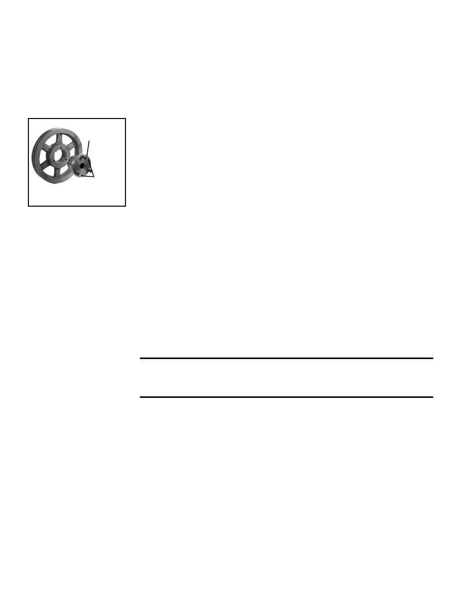
FIGURE 12 - Split
Taper Bushing
(3) Cap
Screws
(2)
Push-Off
Holes
6.4.3 Blower Pulley
Some blower pulleys require the use of a split taper bushing in the blower pul-
ley. These split taper bushings must be loosened in order to remove the pulley.
Follow these instructions to loosen the bushing:
a) Notice that there are three cap screws in the bushing and two holes with-
out screws, called push-off holes. (See
FIGURE 12.)
b) Remove the three cap screws.
c) Put two of the cap screws into the two push-off holes. Tighten these two
screws evenly until the pulley is loosened.
d) Pulley may now be removed from the shaft.
6.4.4 Blower Bearings
The blower on systems with less than a 10 HP motor are permanently lubri-
cated cartridge ball bearings and do not require greasing. The bearings on sys-
tems with a 10HP motor are pillow block ball bearings and are equipped with a
grease fitting. Refer to Form O-MAPS for maintenance instructions.
7.2 Supply Wiring
7. Electrical and
Wiring
All electrical wiring and connections, including electrical grounding MUST be
made in accordance with the National Electric Code ANSI/NFPA No. 70 (latest
edition). In addition, the installer should be aware of any local ordinances or
electric company requirements that might apply.
Check and tighten all electrical terminals.
CAUTION: If any of the original wire as supplied with the appliance
must be replaced, it must be replaced with wiring material having
a temperature rating of at least 105°C. See Hazard Levels, page 2.
Each unit has a custom wiring diagram in the control compartment. All optional
electrical components ordered with the unit are shown on that wiring diagram.
Codes for those options are listed across the bottom of the diagram. To identify
option codes, see the list in the
APPENDIX, page 58.
After all field wiring is completed, seal all electrical entrances.
7.1 General, Wiring
Diagram, and
Unit Wiring
Requirements
6.4.5 Blower Rotation
6.4 Blowers (cont'd)
6. Mechanical
(cont'd)
Through-the-Base
Electrical Entrance
6.4.2 Adjusting Blower Speed (cont'd)
Check the rating plate for the supply voltage and current requirements. Run
a separate line voltage supply directly from the main electrical panel, making
connection at the factory-supplied disconnect switch. The built-in disconnect
switch requires copper wiring with ampacity based on 60°C maximum tem-
perature rating at the line side terminals. All external wiring must be within
approved conduit and all other external wiring must have a minimum tempera-
ture rise rating of 60°C. Run conduit so that it does not interfere with the sys-
tem access panels. See
FIGURE 2A or 2B, page 7 or 8, for location of supply
wiring entrance.
Or, if the system is equipped with an optional through-the-base electrical sup-
ply entrance (Option AVC1), run the wiring from underneath, through the hole
in the cabinet bottom, and up to the disconnect switch.
Each blower housing is marked for proper rotation. Check blower rotation with
the arrow on the housing. If actual rotation is not correct, interchange the two
wires on the 3-phase supply connections at the terminal block. Do not change
load side wiring.