Controls, 1 digital control systems, Electrical and wiring (cont'd) – Reznor MAPS II Unit Installation Manual User Manual
Page 28
Form I-MAPS II, Page 28
Compressor Protection
A low pressure cutoff (LPCO) switch is used for protection against compressor
damage due to a loss of system charge. This protection prevents short cycling
on the internal overload (IOL) which can pump the oil out of the compressor.
All compressors located in positions A, B, and C and the compressor in posi-
tion D on Sizes 139 and 164 have manual reset high pressure cutouts.
The hot gas bypass option provides expanded
compressor modulation at low outside air temper-
atures. It is factory set; however, the factory adjust-
ment should be checked at startup. To check the
valve operation and/or make field adjustments, it
is necessary to simulate a light load condition.
Check Bypass Valve Setting - Connect a pressure
gauge to the suction line and block the entering
air to the evaporator coil. Suction pressure will
drop, and the hot gas bypass valve should begin
to open at approximately 75 psig. The valve has a range of 6 psig and will be
fully open at 69 psig. When the valve begins to open, it will be hot to the touch.
To adjust the pressure, remove the cap and turn the adjusting stem clockwise
to increase the setting pressure and counterclockwise to decrease the setting
pressure. Make adjustments in small increments. Allow five minutes between
adjustments for the system to stabilize. When finished, replace the cap on the
adjustment stem and remove the pressure gauge.
8.1 Digital Control Systems
All systems have a unit-mounted, factory-wired, 24-volt DDC controller that is
specifically designed to control cooling (3 stages) and heating based on dis-
charge air temperature, outdoor air temperature, dewpoint, and enthalpy.
The integrated display will show the current discharge air temperature, outdoor
air temperature, dewpoint, and enthalpy; which outputs are enabled; and the
mode of operation. The controller allows the user to change setpoints, change
prop bands, and adjust the time clock (Option BHB1 with Option D12; standard
with Option D12A). For instructions on changing or adjusting the controller, see
the forms supplied in the literature envelope.
The digital controller monitors or provides the following: air proving switch, low
limit protection, anti-cycle protection, minimum on/off times, gas valve modu-
lation, and electric heat staging. Controllers may be equipped with optional
cards for use with Johnson N2 (Option BHB2) or LON (Option BHB3) Building
Automation System.
8. Controls
Both control options provide the functions listed below.
• Discharge air reset with heating/cooling setpoints
• Zone heating/cooling setpoints
• Reheat override options (disable reheat on call for cooling)
• Cooling lockouts (enthalpy)
• Discharge air reset based on outdoor dry bulb (linear reset)
FIGURE 16 - Programmable
Controllers
Summary of Control Features
available on all MAPS II Models
Reference NOTES:
For unit-mounted control
location, refer to
FIGURE
20 or 21 on pages 32-33.
7. Electrical and
Wiring (cont'd)
7.7 Compressors
(cont'd)
CAUTION: An
operating bypass
valve is very hot to
the touch.
FX05 Controller
in Option D12
FX06 Controller
in Option D12A
In addition, Option D12A control system provides.
• Real time clock function built in with 8 event, 7-day
schedule
• 9 menu selections for setpoint adjustments and unit status
• Optional remote display and remote space temperature
setpoint adjustment
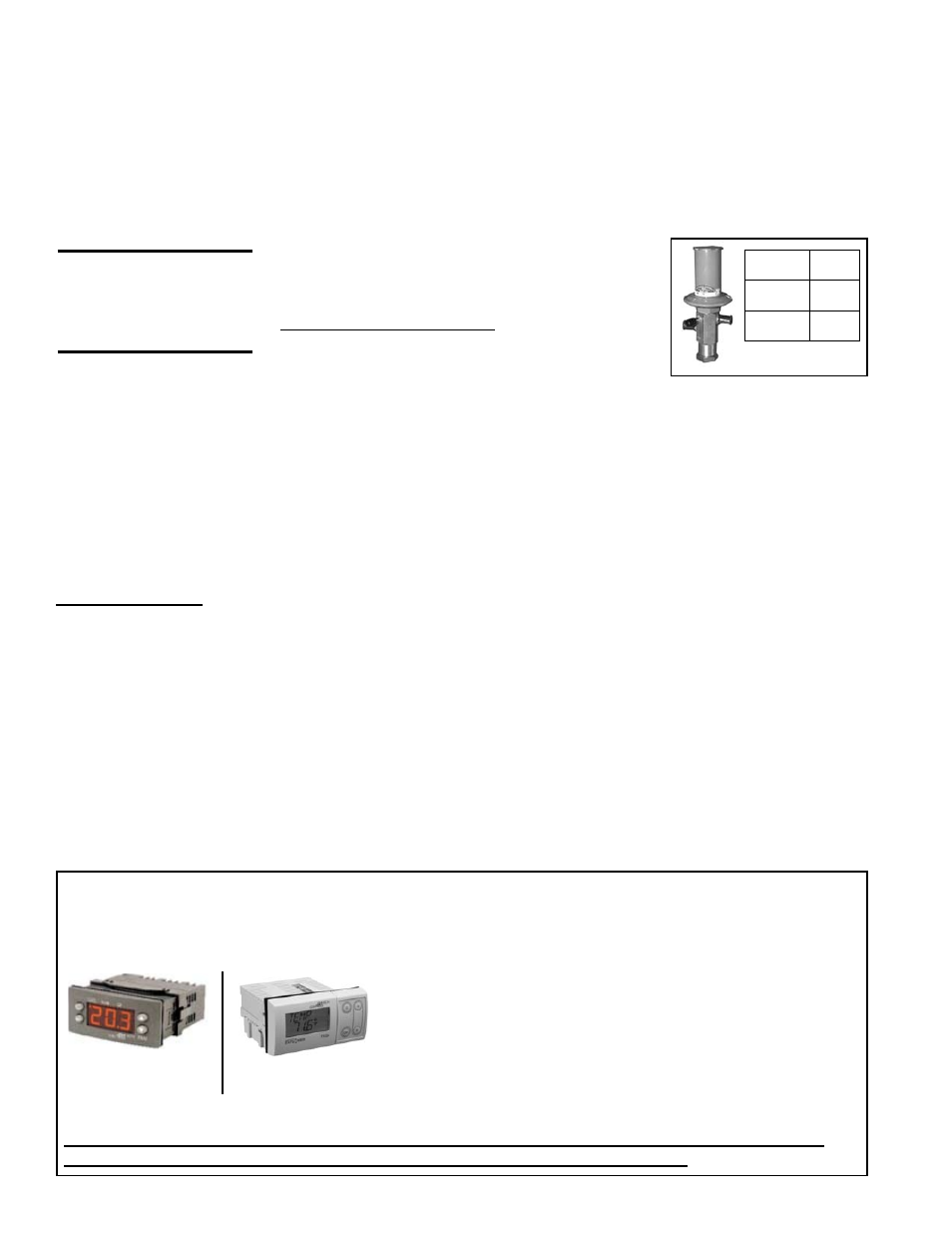
Optional Hot Gas
Bypass
FIGURE 15 - Optional
Hot Gas Bypass Valve
Adjustment
Range
0-80 PSI
Factory
Setting
75 PSI
PSI per
Turn
7.5
REFERENCE: For controller instructions, see either Form CP-MAPS D12 w/FX05 or CP-MAPS
D12A w/FX06 in the literature envelope or download from www.RezSpec.com.