Reznor MAPS II Unit Installation Manual User Manual
Page 37
Form I-MAPS II, P/N 206131 (Rev 13), Page 37
���
���
���
���
���
����
���
����
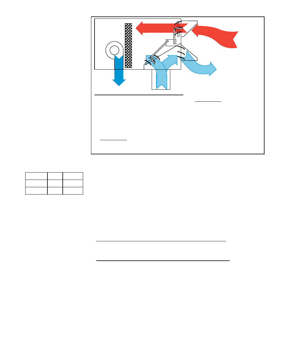
9.1.2 Economizer
Options
FIGURE 29 -
Component Locations
of Economizer Air
Control Options
AR2E and AR2F
Legend (applies to Option AR2E and AR2F):
NOTE: Damper linkage
may not provide
adequate air balance
of return and outside
air quantities. Compare
return duct and outside
air inlet hood pressure
drops to determine
balancing requirements.
Operating Sequence
with Economizer
Option AR2E
Option AR2F - Dry Bulb Econ-
omizer Control provides free
cooling for dry climates.
(
10) Barometric Relief Dampers
(
12) Outside Air Enthalpy Sen-
sor, Option AR2E
Outside Air Dry Bulb Sensor,
Option AR2F
(
2) Horizontal Air Intake and Exhaust Air
Openings
(
3) Bottom Return Air Opening
(
4) Outside Air Intake Dampers
(
5) Return Air Dampers
(
6) Modulating Damper Motor
(
9) Economizer Controls
Option AR2E - Reference Enthalpy Con-
trol provides free cooling with variable
building loads for temperate climates.
On a call for low stage cooling
1. The blower motor is energized.
2. With the outdoor enthalpy less than the return air enthalpy:
a) The "A" and "B" cool circuits are locked out.
b) Dampers are positioned by the economizer and mixed air sensor.
3. With outdoor air enthalpy higher than the return air enthalpy:
a) The "A" cool circuit is energized.
b) Dampers are positioned for minimum outside air.
c) On a call for high stage cooling, the "B" circuit is staged appropriately.
FX05/FX06 Controller
Setting Change
Display New Default
EN1
20
29
OC1
58°F 68°F
With the economizer and return air, the "mixed" air temperature sensed at the
evaporator coil is raised. Lowering the EN1 and OC1 setpoints on the control-
ler as shown in the table, will allow the enthalpy controller on the economizer to
take over control of mechanical cooling. For instructions on setting the control-
ler, refer to the control instruction sheet in the literature envelope.
Also, check the enthalpy setting on the economizer; it needs to be at the
"D" setting. Adjust the minimum position potentiometer for the mixture of air
required for the installation.
(NOTE: The EXH, DCV1, and CDV2 functions on the control are not used.)
9.1.3 Energy
Recovery Module
Options
Energy recovery modules are shipped separately for field installation. Modules
include an enthalpy wheel, a supply air blower, an exhaust blower, an intake
hood, and an exhaust hood with a gravity damper. Energy recovery modules
are identified as Option ER and are selected by CFM. The modules also have a
variety of options. In addition to the Option ER energy recovery module, either
air control Option AR2B or AR2A is required. See
FIGURE 30A or FIGURE
30B for application and control components.
Follow the installation instructions shipped with the module.