3 gas heat module - models rdca and rdda (cont'd) – Reznor MAPS II Unit Installation Manual User Manual
Page 44
Form I-MAPS II, Page 44
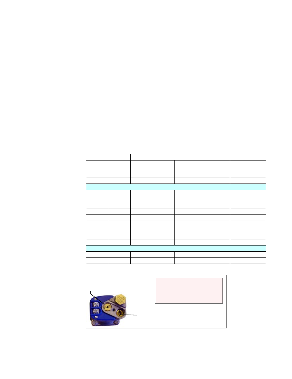
FIGURE 37 - Top
View of Electronic
Modulating/
Regulating Valve in
Option AG57, 6:1
modulating turndown
High Fire
Adjustment Screw
Low Fire Adjustment Screw
DO NOT ADJUST pressure
at the modulating valve;
contact the factory service
department.
Altitude
Natural Gas
Feet
Meters
Minimum "Fire" OUTLET
Gas Pressure for 2/3
Burner Section *
Full Rate INLET Gas Pressure at
Single-Stage Valves with both
Burner Sections Operating
Full Rate OUTLET
Gas Pressure
Tolerance
(-.1 to +.2 " w.c.)
(-.15 to +.15 " w.c.)
(-.15 to +.15 " w.c.)
UNITED STATES
0-2000
0-610
1.20" w.c.
4.5" w.c.
3.5" w.c.
2001-3000
611-915
1.05" w.c.
4.1" w.c.
3.1" w.c.
3001-4000 916-1220
1.00" w.c.
4.0" w.c.
3.0" w.c.
4001-5000 1221-1525
.95" w.c.
3.8" w.c.
2.8" w.c.
5001-6000 1526-1830
.90" w.c.
3.7" w.c.
2.7" w.c.
6001-7000 1831-2135
.86" w.c.
3.6" w.c.
2.6" w.c.
7001-8000 2136-2440
.84" w.c.
3.5" w.c.
2.5" w.c.
8001-9000 2441-2745
.80" w.c.
4.4" w.c.
2.4" w.c.
9001-10000 2746-3045
.78" w.c.
3.3" w.c.
2.3" w.c.
CANADA
0-2000
0-610
1.20" w.c.
4.5" w.c.
3.5" w.c.
2001-4500 611-1373
2.80" w.c.
3.8" w.c.
2.8" w.c.
*The 1/3 burner outlet pressure will be slightly higher; it does not need to be set.
The input and/or the capacity of the gas heat section changes with altitude.
The tables below list inputs and capacities at altitudes from sea level to 10,000
ft (3045M).
High Altitude
Capacity Changes
9.3.2 Gas Heat Module - Mechanical (cont'd)
9.3.2.1 Gas Piping and Pressures (cont'd)
9.3 Gas Heat Module - Models RDCA and RDDA (cont'd)
9. Optional
Equipment
including
Heat Sections
(cont'd)
Turn the manual valve off. Connect the manometer to the second valve and
repeat to check the outlet pressure of the other single-stage gas valves. High-
fire outlet pressure should be the same for each valve.
If equipped with Option AG57, the furnace has a modulating valve to provide
6:1 turndown. To measure the minimum fire outlet pressure, check the outlet
pressure of the single-stage valve at the 2/3 burner (See
FIGURE 33B or
35B). Connect the manometer at the same pressure tap as when measuring
high fire outlet pressure. Disconnect one of the lead wires to the modulating
valve. With the unit at full fire, measure the outlet gas pressure at the single-
stage valve. Gas pressure should be as listed for "Full Rate Inlet Pressure" in
the table below. (Modulating valve is a reverse acting valve; 0-6 is high fire and
15-24 is low fire.) If pressure is not correct, contact the factory. This setting is
not field adjustable. After checking pressure, be sure to reconnect the wire to
the modulating valve.
For reference purposes only, pressures by altitude are shown in the table below.
CONTACT THE FACTORY SERVICE DEPT IF PRESSURE IS INCORRECT.
DO NOT ADJUST.