Reznor MAPS II Unit Installation Manual User Manual
Page 29
Form I-MAPS II, P/N 206131 (Rev 13), Page 29
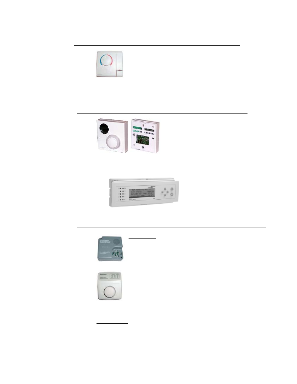
Optional Control used only with System Control Option D12 (FX05 Controller)
Wall-Mounted Space
(Zone) Temperature
Sensor, Option CL53,
P/N 207239 (or Op-
tion RT11 if factory
mounted on an
optional console,
Paragraph 8.2)
Control works with either cooling or heating, providing zone tem-
perature sensing, occupied setpoint boost (-3° cooling; 4° heat-
ing) and unoccupied override button, and LED fan and alarm
status for cooling. Provides space temperature identification only
(no space adjustment).
Depending on how it is ordered, the control is shipped separately for field instal-
lation or factory-mounted on a shipped-separate console. Follow the instruc-
tions supplied with the control and the wiring diagram on the unit.
Optional Controls/
Sensors with Options
D12 and D12A
If unsure which options are on the unit being installed, check the wiring dia-
gram for the option codes.
Optional Controls used only with System Control Option D12A (FX06 Controller)
The wall or console mounted sensor should be
located on an interior wall (avoid direct place-
ment in the sun) with the wall opening insulated
to prevent cold drafts. Locate the sensor where
it will sample representative space air.
The optional space sensor with setpoint adjust
transfers the data back to the unit controller. The sensor requires 24VAC power
and two wire communication. See the unit wiring diagram for wiring details.
Wall-Mount Space
Air Sensor, Option
CL67, P/N 222052
(or Option RT14 if
factory-mounted on
an optional console,
Paragraph 8.2)
Optional Remote Medium
User Interface, Option
RB2A, P/N 223125 (or
Option RT15 if factory-
mounted on an optional
console, Paragraph 8.2)
The wall or console mounted user inter-
face provides access to all controller set-
point and commands except test mode.
Follow the instructions supplied with the
control. Wire according to the wiring dia-
gram on the unit.
Option DT5, Outside
Air Relative Humidity
Transmitter,
P/N 206081
Option DT5 - The sensor is factory-mounted in the outside air
intake and sequences compressor operation based on outdoor
dewpoint. It is recommended for humid and temperate climates.
(NOTE: This control is standard on Models RDA, RDDA, REDA
and other units with reheat Option AU25.)
Option BNC1,
Damper Changeover
Option BNC1 - Control is unit mounted. Used in conjunction with a customer-
supplied time clock, control overrides the outside air damper during unoccu-
pied mode. Setup and setback setpoints are provided through the program-
mable control. Time clock contacts are closed during occupied mode.
Option CL47, Room
Dehumidistat,
P/N 177231 (or Option
RT13 if factory-
mounted on an
optional console)
Option CL47 - Uses standard control reheat sequences, except
that the zone relative humidity input controls the reheat outputs.
The relative humidity controller enables reheat upon a rise in
relative humidity.
Control is shipped separately for field installation. Follow the
instructions supplied with the control. Wire according to the wiring diagram on
the unit.
Optional Controls used with either System Control Option D12 (FX05) and D12A (FX06)
Discharge
Temperature Sensor
The discharge sensor element on cooling only or cooling with reheat systems
(Models RCA/RDA) is attached to the discharge opening of the system. On
systems with a heat section (Models RDCA/RDDA/RECA/REDA) or Models