Figure 15. 1/2 duty drive example waveform timing, Lcd controller 1/3 duty cycle drive example, Figure 16. 1/3 drive example display connection – Maxim Integrated MAXQ Family Users Guide: MAXQ2000 Supplement User Manual
Page 83: Maxq family user’s guide: maxq2000 supplement
MAXQ Family User’s Guide:
MAXQ2000 Supplement
COM1
COM2
COM0
SEG2
SEG1
SEG0
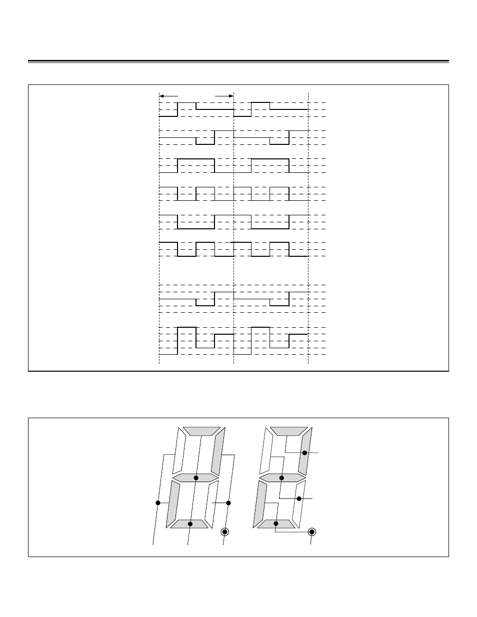
Figure 16. 1/3 Drive Example Display Connection
1 FRAME (f
FRAME
)
V
LCD
V
LCD1
GND
COM0
V
LCD
V
LCD1
GND
SEG0
V
LCD
V
LCD1
GND
COM1
V
LCD
V
LCD1
GND
SEG1
V
LCD
V
LCD1
GND
SEG2
V
LCD
V
LCD1
GND
SEG3
V
LCD
1/2 V
LCD
GND
-1/2 V
LCD
-V
LCD
COM0–SEG1
(ON)
V
LCD
1/2 V
LCD
GND
-1/2 V
LCD
-V
LCD
COM0–SEG0
(OFF)
Figure 15. 1/2 Duty Drive Example Waveform Timing
LCD Controller 1/3 Duty Cycle Drive Example
In this example, SEG0 through SEG2 are used to drive the LCD segments. The segments and common signals are connected as shown
in Figure 16.
Maxim Integrated
83
See also other documents in the category Maxim Integrated Hardware:
- DS80C390 (58 pages)
- DS5001FP (26 pages)
- MAX1416 (14 pages)
- MAX5865 (18 pages)
- DS33Z41 (167 pages)
- MAX1202 (7 pages)
- USBTO232 (31 pages)
- HFAN-09.5.0: Pattern Creator/Converter Software (8 pages)
- MAX-IDE MAXQ Microcontrollers (11 pages)
- MAX6876 Power-Supply Tracker/Sequencer (6 pages)
- MAX6877 Power-Supply Tracker/Sequencer (3 pages)
- 78Q8430 ARM9(920T) Linux Driver Diagnostic Guide (19 pages)
- 78Q8430 Software Driver (54 pages)
- 78Q8430 ST 5100/OS-20 with NexGen TCP/IP Stack (28 pages)
- 6612_OMU_S2_URT_V1_13 (56 pages)
- 6612_OMU_S2+2_URT_V1_14 (58 pages)
- 71M6511 Power Meter IC Family Software (137 pages)
- 71M65xx ADM51 ICE Safety Notice (2 pages)
- 71M6511 2-Layer Demo Board (2 pages)
- 71M6511 4-Layer Demo Board (2 pages)
- 78Q8430 Linux Driver ARM Platform (22 pages)
- 71M6513 Demo Board (2 pages)
- 71M6521DE Energy Meter IC Family Software (138 pages)
- 71M6521 Demo Board (2 pages)
- 71M6531 Demo Board (2 pages)
- 71M6531 Energy Meter IC Family Software (116 pages)
- 71M6533 Demo Board (2 pages)
- 71M6534H Demo Board (2 pages)
- 71M6515H Demo Board (2 pages)
- 73S1209F Evaluation Board (2 pages)
- 73S12xxF (38 pages)
- 73S12xxF Software (93 pages)
- 73S1210F Evaluation Board Lite (2 pages)
- 73S1210F Evaluation Board (2 pages)
- 73S1210F Multi-SAM Evaluation Board Lite (2 pages)
- 73S12xxF USB-CCID Linux DFU Host Application (8 pages)
- 73S1215F Device Firmware Upgrade Host Driver/Application (10 pages)
- 73S12xxF USB-CCID Host GUI (22 pages)
- 73S1215F Windows XP 32 USB CCID and DFU Drivers (15 pages)
- 73S1215F CCID USB Linux Driver (16 pages)
- 73S1215F Evaluation Board (2 pages)
- 73S1215F Evaluation Board Lite (2 pages)
- 73S1217F Evaluation Board (2 pages)
- 73S1217F Evaluation Board Lite (2 pages)
- MAXQ Family (216 pages)