Addendum to section 10: serial i/o module, Table 15. serial uart input and output pins, Table 16. serial uart control registers – Maxim Integrated MAXQ Family Users Guide: MAXQ2000 Supplement User Manual
Page 51: Addendum to section 10: serial i/o (uart) module, Maxq family user’s guide: maxq2000 supplement
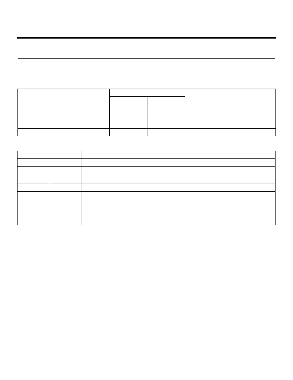
ADDENDUM TO SECTION 10: SERIAL I/O (UART) MODULE
The MAXQ2000 provides up to two serial UART modules (Serial 0 and 1 in the 68-pin package, Serial 0 in the 56-pin package), which
operate as described in the MAXQ Family User’s Guide. Table 15 shows the associated pins and Table 16 shows the associated reg-
isters for these UARTs.
Serial UART Example: Asynchronous 10-Bit Output at 115,200 Baud
move SCON0.6, #1
; Set to mode 1 (10-bit asynchronous)
move SCON0.4, #1
; Enable receiver
move SMD0.1, #1
; Baud rate = 16 x baud clock
move PR0, #45E8h
; PR0 = 2^21 * 115200 / 13.5MHz (crystal)
move SCON0.0, #0
; Clear received character flag
move SCON0.1, #0
; Clear transmit character flag
Loop1:
move Acc, #'0'
; Start with '0' character
move LC[0], #10
; Transmit from '0'-'9'
Loop2:
move SBUF0, Acc
; Send character
Transmit:
move C, SCON0.1
; Check transmit flag
jump NC, Transmit
; Wait for transmit to complete
move SCON0.1, #0
; Clear transmit flag
add #1
; Increment character by 1
djnz LC[0], Loop2
jump Loop1
MAXQ Family User’s Guide:
MAXQ2000 Supplement
PIN NUMBER
SERIAL UART FUNCTION
68-PIN
56-PIN
MULTIPLEXED WITH PORT PIN
Serial Port 0 Receive—RXD0
53
44
P7.1
Serial Port 0 Transmit—TXD0
52
43
P7.0
Serial Port 1 Receive—RXD1
36
—
P5.2
Serial Port 1 Transmit—TXD1
37
—
P5.3
Table 15. Serial UART Input and Output Pins
REGISTER
ADDRESS
FUNCTION
SCON0
M2[06h]
Serial Port 0 Control Register. Serial port mode, receive enable, 9th bit control, and interrupt flags.
SBUF0
M2[07h]
Serial Port 0 Data Buffer. Input and output data buffer.
SMD0
M2[08h]
Serial Port 0 Mode Register. Controls baud rate, interrupt enable, and framing error detection.
PR0
M2[09h]
Serial Port 0 Phase Register. Contains counter reload value for baud rate generation.
SCON1
M3[06h]
Serial Port 1 Control Register. Serial port mode, receive enable, 9th bit control, and interrupt flags.
SBUF1
M3[07h]
Serial Port 1 Data Buffer. Input and output data buffer.
SMD1
M3[08h]
Serial Port 1 Mode Register. Controls baud rate, interrupt enable, and framing error detection.
PR1
M3[09h]
Serial Port 1 Phase Register. Contains counter reload value for baud rate generation.
Table 16. Serial UART Control Registers
Maxim Integrated
51