EVCO EVF818P9 User Manual
Page 51
EVCO S.p.A.
EVF818 | Installer manual ver. 1.0 | Code 144F818E104
page 51 of 76
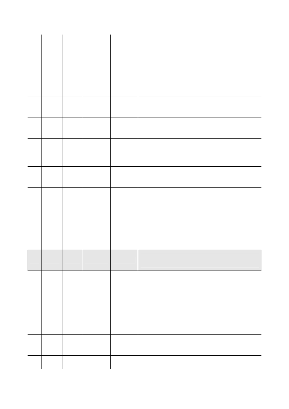
u1
0
1
- - - -
0
utility managed by the output K8 (15)
0 = pump down valve (in this case, parameter u12 will
have meaning)
1 = alarm output
u2
0
1
- - - -
0
enabling of cabinet light switch-on/off in manual mode
during "stand-by" status (16)
1 = yes
u5
-99
99
°C/°F (1)
20
cabinet temperature over which the door heating elements
are off (4)
u6
1
240
min
5
switching on UV light for sterilisation cycle duration
u7
-99
199
°C/°F (1)
40
needle probe heating end temperature (temperature
detected by the needle probe); see also parameter u8
u8
1
240
min
2
maximum duration of needle probe heating; see also
parameter u7
u11
0
1
- - - -
0
utility managed by the output K7 (15)
0 = cabinet light (in this case, the DEEP FREEZING key
and parameters i0 and u2 will assume significance)
1 = UV light (in this case, the DEEP FREEZING key and
parameter u6 will assume significance)
u12
0
999
s
10
compressor switch off delay from pump down valve
deactivation (pump down in switch-off) (17)
Par.
Min.
Max.
Unit
Default
Serial
communication
(RS-48
serial
port
with
MODBUS communication protocol)
L0
0
1
- - - -
0
operating mode
0 = slave (in this case, it will be possible to connect
Parameters Manager set-up software system, to the
monitoring and surveillance system of the RICS
plants or to the data recording device, to download
the
recorded
data
to
the
port
(via
USB)
EVUSBREC01).
1 = master (in this case, it will be possible to connect the
print module PM 100A X9S001 to the port)
L1
1
240
min
5
print interval during blast chilling or during deep freezing
L2
1
240
min
15
print interval during storage