Electrical: charging circuit, Charging system diagnosis, Cub cadet commercial z-wing – Cub Cadet Z-Wing User Manual
Page 82
Cub Cadet Commercial Z-Wing
78
34.
ELECTRICAL: CHARGING CIRCUIT
34.1. The output of the charging system reaches the
“hot” lug on the starter solenoid through the vio-
let wire from the regulator / rectifier.
See Figure 34.1.
34.2. At this point (hot lug), charging system output is
transferred directly to the heavy-gauge cable.
The other end of the heavy gauge cable is con-
nected directly to the positive post on the bat-
tery.
35.
CHARGING SYSTEM DIAGNOSIS
35.1. D.C. voltage output of the regulator rectifier is
easily checked by connecting a DVOM, set to
read D.C. voltage between the violet wire and a
good ground such as the negative battery post
or engine block. See Figure 35.1.
35.2. The voltage read at this point, with the engine
running at 3,600 RPM, should be more than bat-
tery voltage, but less than 14.7 V. Higher voltage
indicates a bad regulator / rectifier.
35.3. Voltage read at this point with the engine turned-
off will be whatever is in the battery.
35.4. Amperage out-put of the charging system
requires a Ammeter to be wired in-series with
the stator circuit (white wires), or the use of an
inductive ammeter. Output will vary with load.
this charging system has a nominal capacity of
15 Amps.
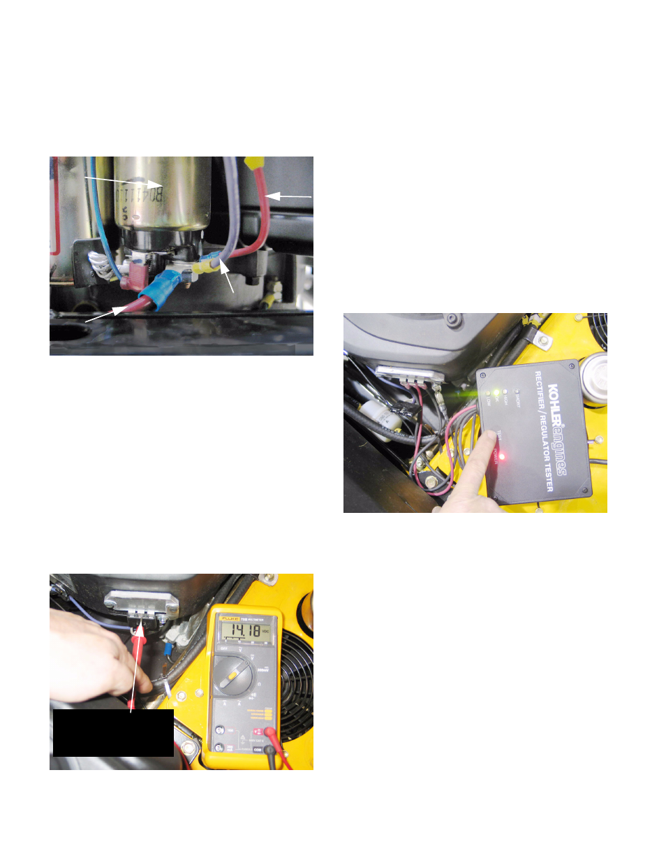
35.5. The regulator / rectifier can be tested in isolation
from the rest of the system using a tester manu-
factured by Kohler (P/N: 25 761 20). Following
Kohler’s instructions: See Figure 35.5.
•
Unplug the harness connector from the regulator
/ rectifier, being careful not to short the center
spade to either of the outer spades in the pro-
cess.
•
Connect the wire with the clip on it to a good
ground. The L-shaped strap with zinc-coated
screw that connects the regulator / rectifier to the
engine block is an important ground, and a
clean, firm connection should be maintained.
•
Connect the red lead to the center, output spade
on the regulator / rectifier.
•
Connect the two black leads to the outer spades
on the regulator rectifier.
•
Plug the tester into a 110V base plug, turn-on
the power, and press the test button.
•
Regulator / rectifier condition is indicated by the
status light.
Figure 34.1
Heavy gauge red battery cable
12 gauge violet wire
from regulator / rectifier
Red wire
with fuse
: unused
Starter solenoid
Figure 35.1
Regulated D.C. voltage:
center spade on
regulator / rectifier
Figure 35.5