Cub cadet commercial z-wing – Cub Cadet Z-Wing User Manual
Page 21
Cub Cadet Commercial Z-Wing
17
NOTE: All four sets of hinge locks and brackets
are identical: the parts are interchangeable left-
to-right and front-to-rear.
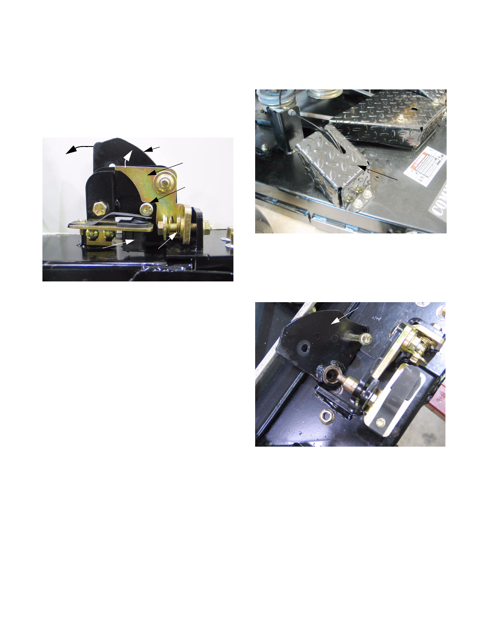
10.3. When the wing lift is activated, all four cables,
hinge locks, and lift mechanisms should work in
unison: See Figure 10.3.
•
The force applied through the cable rotates the
cable bracket inward.
•
The socket head cap screw attached to the
cable bracket moves upward, releasing the
plunger on the safety switch and rotating the
hinge lock clear of the corner of the deck hinge
•
The force of a compression spring keeps the
hinge lock applied when the cable is slack.
•
When the spring is compressed and the hinge
lock is clear of the hinge, the cable will begin to
lift the deck wing.
•
A clutch within the actuator prevents over-travel
when the wings reach the fully raised position.
•
The safety switches prevent the operation of the
PTO with the deck wings raised.
•
Proper adjustment is very important: refer to the
DECK WING CABLE ADJUSTMENT section of
this manual for the correct procedure.
•
Proper hinge alignment is very important. If a
hinge becomes bent or damaged, it must be
repaired before the mower is used.
Figure 10.3
Cable bracket
Hinge lock
Socket-head
cap screw
Wing position switch Compression spring
10.4. The lift mechanism can be reached by removing
the lift wing shield using a 9/16” wrench.
See Figure 10.4.
10.5. If the cable bracket is to be removed, it can be
unbolted with the cable attached using two 9/16”
wrenches. Once loose, the cable can be discon-
nected from the bracket. See Figure 10.5.
NOTE: The bolt and bushing that hold the
bracket are also the pivot point for the deck
wing.
Figure 10.4
Lift wing shield
Figure 10.5
Cable bracket
(unbolted)