Cub cadet commercial z-wing – Cub Cadet Z-Wing User Manual
Page 6
Cub Cadet Commercial Z-Wing
2
2.3.
Precautions:
•
Disable the engine while working on the cutting
deck: Disconnect the sparkplug leads, discon-
nect the negative battery cable, and remove the
key from the key switch.
•
Allow the engine to cool thoroughly before work-
ing near the exhaust system.
•
Protect hands while working on sharp objects
like blades using gloves or rags.
2.4.
With the wings raised the outer blades are easily
accessible for service. The center blade is as
accessible as it would be on a conventional
deck. Lift and safely support the mower to reach
the center blade. See Figure 2.4.
2.5.
The blades can be removed from the blade
mount assembly using a pair of 9/16” wrenches.
See Figure 2.5.
2.6.
When performing any blade or spindle service,
inspect the spindles, pulleys, and belts for wear
or damage.
2.7.
Inspect the hardware that secures the blades to
the blade mount assemblies.
•
Replace the locking nut if the locking feature has
degraded.
•
If the bolt is replaced, use only a grade-8
replacement from a reputable source (Cub
Cadet).
•
Replace the bushing if it shows signs of wear or
damage.
2.8.
On installation, apply a small amount of thread
locking compound such as Loctite 262 (red) to
the threads, and tighten the nuts to a torque of
35-40 ft-lbs (47.5-54 Nm).
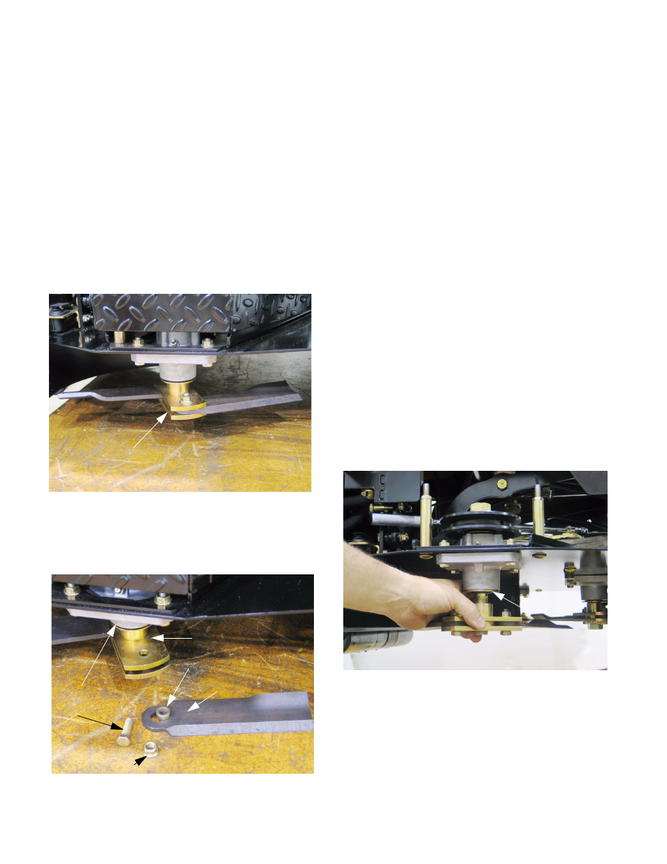
2.9.
If the blade assembly is to be removed for sharp-
ening and balancing, lower the deck to the low-
est cutting position.
2.10. Remove the belt covers using a 9/16” wrench.
2.11. Hold the top of the spindle bolt using a 1 1/8”
wrench and turn the nut off the bottom using a
1 1/8” wrench.
2.12. Slide the blade assembly off the spindle bolt.
NOTE: The steel shield is part of the seal, not
the blade assembly. Do not remove it unless the
spindle requires service.
Figure 2.4
Blade assembly in-place
Figure 2.5
Blade spacer
and upper mounting plate
Bushing
Blade
Self-locking nut
Grade-8 bolt
Steel shield
Figure 2.12
Steel shield