Cub cadet commercial z-wing – Cub Cadet Z-Wing User Manual
Page 49
Cub Cadet Commercial Z-Wing
45
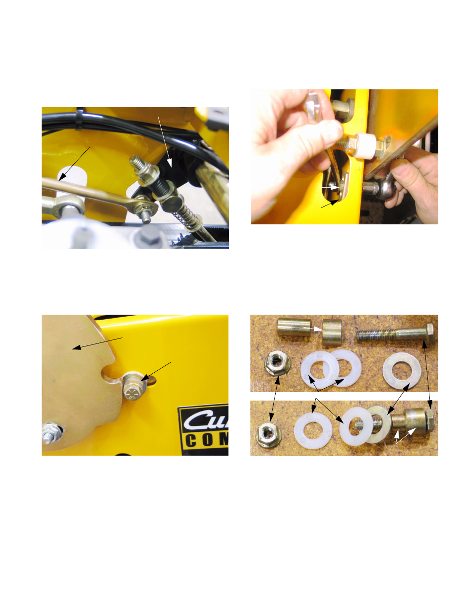
21.31.The interlock is actuated by two steering lock
rods; one for each steering pivot plate. The
steering lock rods extend forward from the out-
put arms on each end of the brake pivot shaft.
See Figure 21.31.
21.32.A post (consisting of a bolt, washers, and spac-
ers) is attached to the other end of the steering
lock rod, guided by a slot in the control housing.
See Figure 21.32.
21.33.When the brake is actuated, the posts slide for-
ward to engage the notches in the rear edges of
the steering pivot plate. When the lap bars are
not in neutral, they also prevent the brakes from
being engaged while the mower is in motion.
Figure 21.31
Steering lock rod
Brake output arm
Figure 21.32
Post
(steering lock)
Steering pivot plate
21.34.The post is easily loosened for adjustment, or
removal using a pair of 1/2” wrenches.
See Figure 21.34.
21.35.A sleeve within a sleeve creates a shoulder
bushing. A steel washer rides on the shoulder to
support a nylon washer that rides outside of the
control housing. A second nylon washer rides
between the steering lock rod and the inside sur-
face of the control housing. See Figure 21.35.
Figure 21.34
Nut
Steering
lock rod
Figure 21.35
Nut Plastic washers Steel washer Bolt
Spacers (sleeves)
Spacers (sleeves)