Cub cadet commercial z-wing – Cub Cadet Z-Wing User Manual
Page 46
Cub Cadet Commercial Z-Wing
42
21.4. Characteristics of brakes that are too tight, con-
tinued:
•
High effort required to pull up the lever that
applies the parking brake. Some “phantom”
resistance may be created by the over-center
action of the interlock linkage.
21.5. Brakes that are too loose are characterized by:
•
Low effort required to pull up the lever that
applies the parking brake. Some “phantom”
resistance may be created by the over-center
action of the interlock linkage.
•
The mower can be pushed (or the wheels
rotated) manually, with the relief valves open
and the brake applied.
21.6. Before making adjustments, make a visual
inspection of the brake linkage. Watch the link-
age as it is being operated, and check for:
See Figure 21.6.
•
Loose, broken, or disconnected linkage compo-
nents.
•
Components that are binding because of corro-
sion, foreign objects, or misalignment (bent
links).
•
Loss of travel because of worn bushings or hard-
ware.
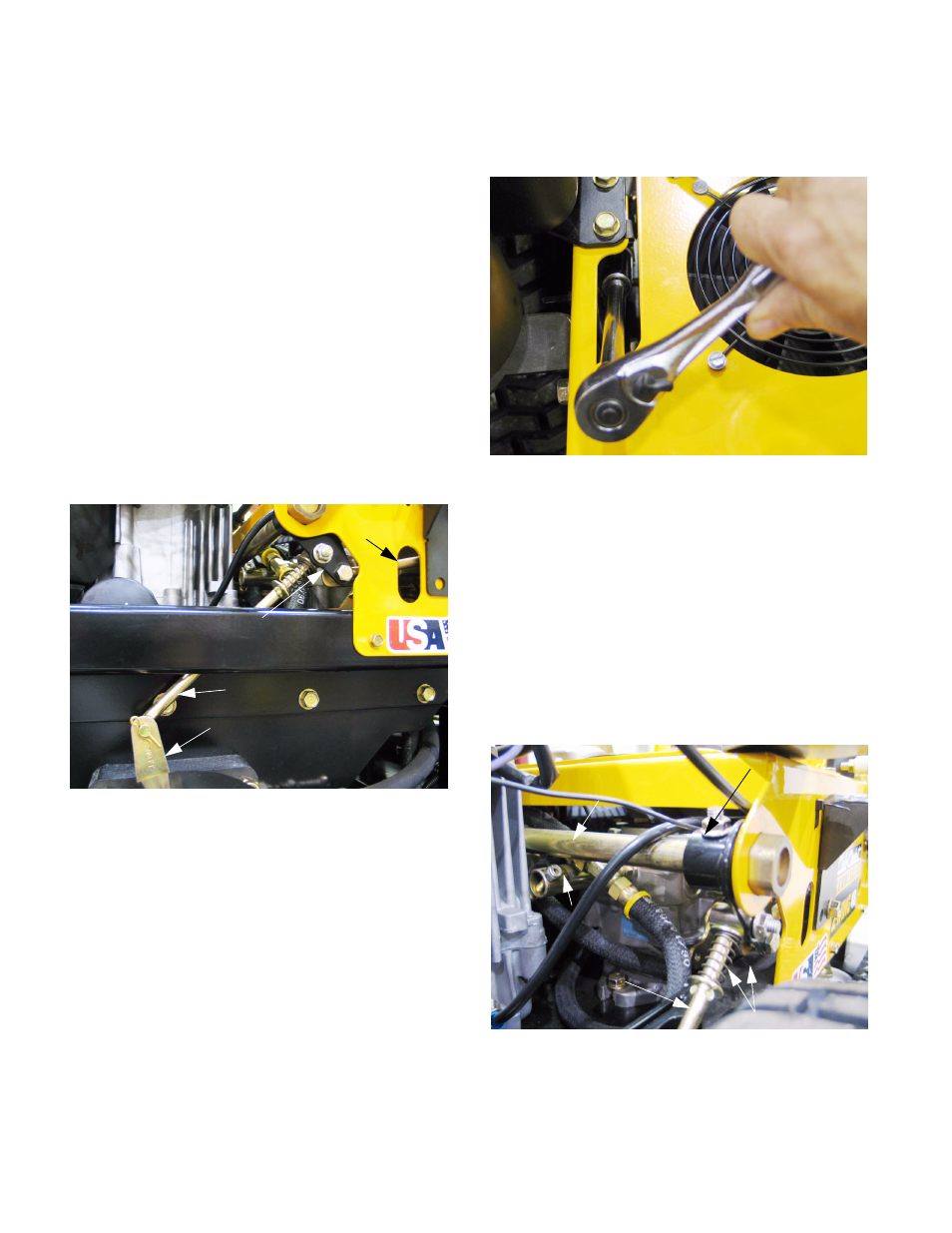
21.7. Each brake adjustment nut can be reached
through an opening between the hydro service
plate and the control housing. See Figure 21.7.
•
There is one adjustment point for each side of
the mower.
•
Adjustment can be made using a deep 9/16”
socket.
21.8. The brake rod is moved by an output arm
attached to the brake pivot shaft assembly.
There is a compression spring on each side of
the contact point. Tightening the nut puts more
pressure on those springs, loosening the nut
reduces the pressure on the springs.
See Figure 21.8.
Figure 21.6
Brake arm
Brake rod
Output arm
Steering
lock rod
Figure 21.7
Figure 21.8
Hydro
relief
valve
Brake rod
Brake pivot
shaft assembly
spring
Compression
Output arm