Cub cadet commercial z-wing – Cub Cadet Z-Wing User Manual
Page 22
Cub Cadet Commercial Z-Wing
18
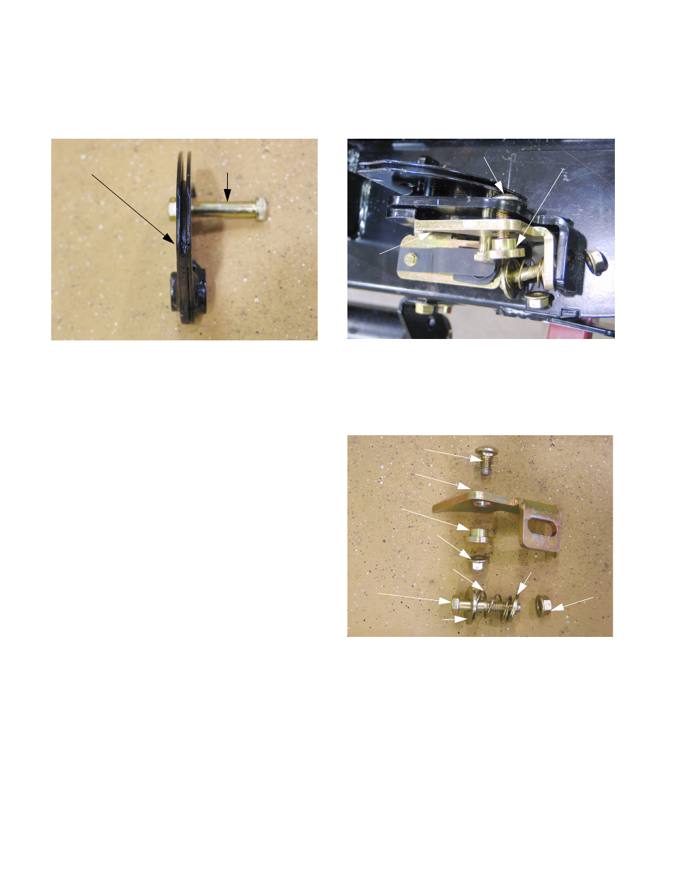
10.6. Orientation: on all four cable brackets, one side
of the bushing shoulder is thicker than the other.
The socket head cap screw always goes on the
side with the thicker shoulder. See Figure 10.6.
10.7. Assembly notes:
•
Reverse the disassembly process to install the
cable bracket.
•
Lubricate the pivot point with anti-seize com-
pound.
•
Apply a small amount of thread locking com-
pound such as Loctite 242 (blue), or replace the
nut if the locking feature of the nut is in question.
Tighten the nut to a torque of 20-25 ft-lbs (27-34
Nm).
•
Confirm correct operation and adjustment of the
wing lift mechanism and all associated safety
features before returning the mower to service.
10.8. To remove the hinge lock, the compression
spring that holds the hinge lock against the
bracket on the deck wing must first be discon-
nected.
10.9. Remove the nut that secures bolt, flat washer,
and the compression spring using a pair of 9/16”
wrenches. The spring will still be captive, but it
can be removed when the hinge lock is unbolted
from the bracket on the deck wing.
10.10.Once the spring is released, remove the nut
from the carriage bolt that secures the hinge lock
and its shouldered bushing to the bracket on the
deck wing. See Figure 10.10.
10.11. The hinge lock assembly can then be removed
from the deck, except for the carriage bolt. The
cable bracket must be removed to release the
carriage bolt. See Figure 10.11.
Figure 10.6
Cable bracket Socket head cap screw
Figure 10.10
Carriage bolt (captive)
Shouldered bushing
Hinge
lock
Figure 10.11
Compression spring Small flat washer
Bolt Self locking nut
Large flat washer
Carriage bolt
Hinge lock
Shouldered
bushing
Self locking nut