Cub cadet commercial z-wing – Cub Cadet Z-Wing User Manual
Page 35
Cub Cadet Commercial Z-Wing
31
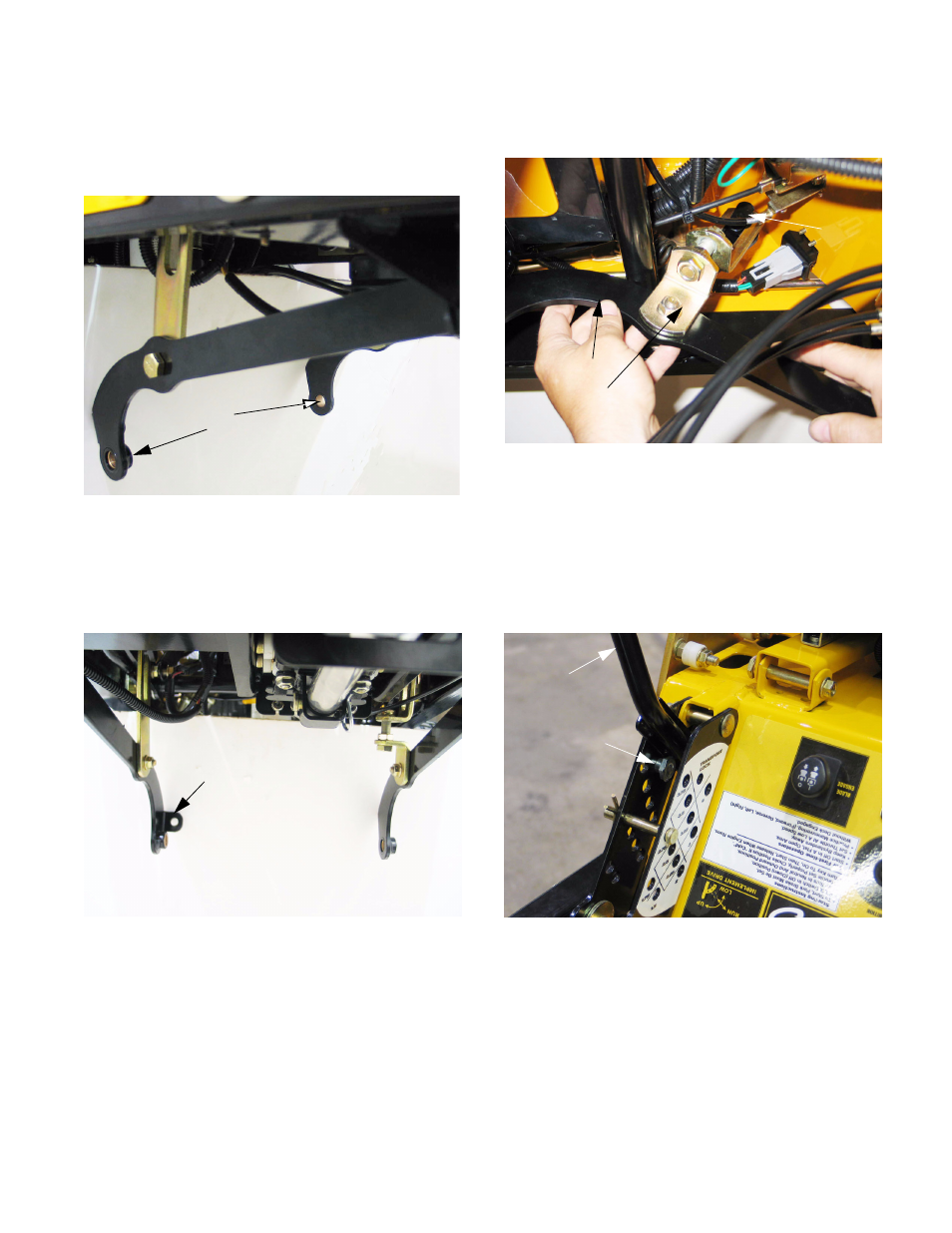
14.4. The deck lift arms and their connection points to
the deck were modified in November of 2005.
The new arms feature a bushing at the connec-
tion point to the cutting deck. See Figure 14.4.
14.5. The bushings on both lift arms are off-set to the
left. The right side arm has a tab for the connec-
tion of a lateral brace that was introduced at mid-
season, 2005. The lateral brace was disused in
November 2005. See Figure 14.5.
14.6. With the front of each lift arm disconnected from
the frame, the lift links can be angled-back so
that the slot in the lift link fits through the T-head
weldment on the lift-shaft assembly.
Figure 14.4
Bushings
Figure 14.5
Connecting point
for lateral brace
14.7. Disconnect and remove each lift arm and lift link
assembly. See Figure 14.7.
14.8. Confirm that the deck height control is in the
highest (Transport Lock) position, minimizing
tension on the lift-assist springs. When raising
the deck lift handle, remove the clevis pin from
above it with caution because the handle will be
under tension from the lift-assist springs.
See Figure 14.8.
Figure 14.7
Lift arm
Lift link
T-head
Figure 14.8
Deck lift handle
Lock position
handle in Transport
securing deck lift
Shoulder bolt