Brake pivot shaft removal, Cub cadet commercial z-wing – Cub Cadet Z-Wing User Manual
Page 50
Cub Cadet Commercial Z-Wing
46
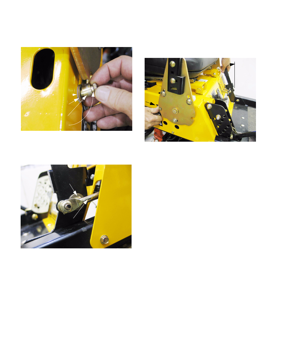
21.36.The steering lock post is installed on the control
housing as illustrated below. See Figure 21.36.
21.37.Adjustment is made by loosening the post and
extending the steering lock rod to the limit of its
travel. See Figure 21.37.
NOTE: Because of the cam-over effect that is
used lock the parking brake in whichever posi-
tion it is set, the rod is at full extension at the
apex of the brake link rod’s travel. The brake link
rod will be centered over the head of the bolt that
the brake handle assembly pivots on.
21.38.When the linkage is in this fully extended posi-
tion, push the post being adjusted as far as it will
go in the notch in the rear edge of the steering
pivot plate and tighten the nut. See Figure 21.38.
21.39.Test the operation of the steering and brake con-
trols, and all related safety features before
returning the mower to service. Tests should be
done in a clear area that is free of hazards,
obstructions, and other personnel.
22.
BRAKE PIVOT SHAFT REMOVAL
NOTE: The brake pivot shaft itself is a 3/4”
(19mm) thick solid steel shaft. As such it is not
likely to require service. The bushings that sup-
port the shaft, the input arm and the output arm
that transfer force through the shaft may require
service.
22.1. Park the mower on a flat, firm, level surface.
22.2. Lift and safely support the mower.
22.3. Remove the rear wheels using a 3/4” wrench.
22.4. Release the parking brake to remove any ten-
sion from the brake linkages.
22.5. Disconnect the top ends of the brake rods from
the arms on both ends of the brake pivot shaft
(input arm on the left end, output arm on the
right end) using a 1/2” wrench.
Figure 21.36
Plastic washer
Steel washer
Large sleeve
Small sleeve
Figure 21.37
Brake link rod
Brake handle pivot
Figure 21.38
Position
handle
here
Slide post into notch