Deck wing and hinge lock, Cub cadet commercial z-wing – Cub Cadet Z-Wing User Manual
Page 20
Cub Cadet Commercial Z-Wing
16
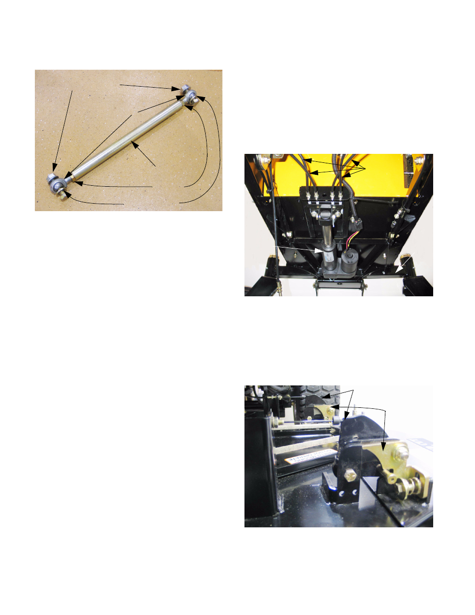
9.11. To adjust the lateral brace: See Figure 9.11.
NOTE: Safety washers prevent the lateral brace
from becoming disconnected if one of the spher-
ical rod-ends fails.
•
Loosen the jam nuts at each spherical rod-end
using an 11/16” wrench before disconnecting the
brace.
•
Disconnect one end of the lateral brace, and
lengthen or shorten the brace as needed by
rotating the tubular center section.
•
Both spherical rod ends are connected to the
center section with right-hand threads, so one
end must be disconnected for adjustment.
•
Reconnect the end, and tighten the jam nuts.
•
If the locking feature of the removed mounting
nut has worn, replace the nut or apply a small
amount of thread locking compound such as
Loctite 242 (blue).
•
Tighten the mounting bolt to a torque of 40 ft.-
lbs. (54.25 Nm).
10.
DECK WING AND HINGE LOCK
NOTE: Mowers produced after mid-season 2005
use a different hinge lock mechanism than the
early 2005 production mowers. While the two
hinge locks are similar in operation, the actual
components differ substantially. The revised
hinge locks will be described in a sub-section
that follows the early hinge lock section.
10.1. How it works: See Figure 10.1.
•
A linear actuator mounted under the floor pulls
on a brace of cables. Each pair of two cables
unlatch and lift one deck wing.
10.2. Each deck wing has two hinge locks and lift
cable brackets, protected by lift wing shields.
See Figure 10.2.
Figure 9.11
Center section
Jam nuts
Spherical rod ends
Mounting nuts / bolts
Safety washers
Figure 10.1
Wing lift
cables
Linear
actuator
Pivot
bar
Figure 10.2
Lift cable brackets
Hinge locks