Cub cadet commercial z-wing – Cub Cadet Z-Wing User Manual
Page 23
Cub Cadet Commercial Z-Wing
19
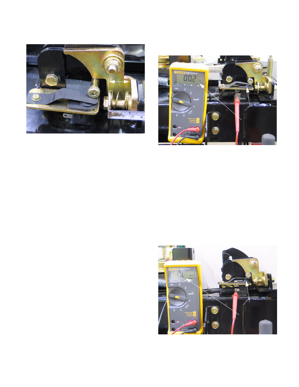
10.12.Assembly notes: See Figure 10.12.
•
Reverse the disassembly process to install the
hinge lock.
•
Lubricate the pivot point (shoulder bushing) with
anti-seize compound.
•
Tighten the nut on the carriage bolt to a torque of
20-25 ft-lbs (27-34 Nm). Apply a small amount of
thread locking compound such as Loctite 242
(blue), or replace the nut if the locking feature of
the nut is in question.
•
Tighten the nut that holds the compression
spring until the distance between the head of the
bolt and the near edge of the bracket on the
deck wing is 1” (2.54 cm), with the hinge lock
pressed firmly against the bracket. Apply a small
amount of thread locking compound such as
Loctite 242 (blue), or replace the nut if the lock-
ing feature of the nut is in question.
•
Confirm correct operation and adjustment of the
wing lift mechanism and all associated safety
features before returning the mower to service.
10.13.There is a safety switch mounted to the rear
hinge on each side of the deck.
•
The switch is actuated by the socket head cap
screw that releases the hinge lock.
•
If the switch contacts of both switches do not
close, the PTO will be disabled.
•
Disabled PTO may be caused by a disconnected
switch, damaged wires, damaged switch, or a
misadjusted switch.
Figure 10.12
1”
10.14.The switch contacts are normally open (N.O.),
meaning that the internal contacts are broken
when the plunger is extended. See Figure 10.14.
•
If the contacts fail to close when the plunger is
depressed, the PTO will not work.
•
If the contacts fail to open when the plunger is
extended, an unsafe condition will exist.
•
The switches should be tested whenever mower
deck maintenance is being performed.
10.15.The switches are mounted to a slotted bracket
using carriage bolts: they are adjustable.
10.16.The switches are correctly adjusted when the
contacts break just as the corner of the hinge
lock clears the corner of the hinge.
See Figure 10.16.
Figure 10.14
Plunger down
Contacts closed
Figure 10.16
Plunger up
Contacts open
Hinge lock
just clears
corner of
hinge