Electrical: engine stop circuit, Cub cadet commercial z-wing – Cub Cadet Z-Wing User Manual
Page 78
Cub Cadet Commercial Z-Wing
74
29.5. Power passes from the PTO switch to the N.O.
contacts on the brake switch through the orange
w/black trace wire. See Figure 29.5.
•
If the contacts are closed (brake applied, plunger
depressed), the current continues through a
plain orange wire to the engine harness connec-
tor.
•
If the contacts are open, the circuit will not com-
plete and power will not reach the starter.
29.6. At the engine harness connector, the orange
wire corresponds to a blue wire that connects to
the trigger spade on the starter solenoid.
29.7. The solenoid and starter receive high-amperage
current through a heavy-gauge red battery cable
connected to the heavy lug on the starter sole-
noid.
29.8. The L terminal directs power to the after-fire
solenoid and the accessory circuits (PTO and
Wing lift) through a red wire when the key is in
the START position.
30.
ELECTRICAL: ENGINE STOP CIRCUIT
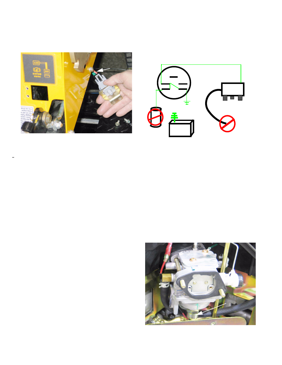
30.1. With the key in the OFF position, Terminals G, M,
and L are connected within the key switch. See
Figure 30.1.
30.2. Terminal G is connected to a green wire that
constitutes the ground circuit. The ground circuit
is connected to the frame of the mower and the
engine block.
30.3. The heavy gauge black cable connected to the
negative post of the battery also leads to the
frame of the mower.
30.4. Terminal L is connected to a red wire that pro-
vides power to the accessory circuits and to the
after-fire solenoid on the carburetor.
30.5. When the engine is running, the after-fire sole-
noid draws power from the charging circuit.
See Figure 30.5.
Figure 29.5
Orange wires=
Starter circuit=
N..O. contacts
Figure 30.1
S
M B
L G
Battery
A-F
Sol.
Key Switch:
OFF
Ignition
Module
Figure 30.5
After-fire
solenoid