Cub Cadet Z-Wing User Manual
Page 76
Cub Cadet Commercial Z-Wing
72
28.27.The harnesses are joined in the order indicated
in the chart: See Figure 28.27.
28.28.Engine harness - magneto: The white wires
connect to the kill tang on each of the two igni-
tion modules.
28.29.Engine harness - after-fire solenoid: The red
wire connects the after-fire solenoid on the bot-
tom of the carburetor. See Figure 28.29.
28.30.Engine harness - alternator: Raw output from
the stator enters the regulator / rectifier through
two white wires, just visible under the flywheel.
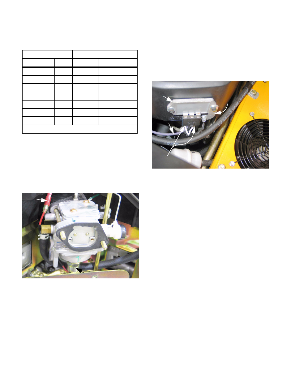
28.31.Engine harness - regulator / rectifier: The regu-
lator / rectifier is mounted near the right front cor-
ner of the engine, extending into the blower
shroud. See Figure 28.31.
•
The violet wire carries charging current to the
battery, via the hot lug on the starter.
•
The L-shaped strap must maintain good ground
contact with the engine block.
•
Raw stator output enters through white wires.
28.32.The amperage out-put of the alternator can be
tested using an automotive VAT tester, a
Briggs& Stratton DC shunt (P/N 19359), or a
suitable amp meter.
•
D.C. output should be 12.5 - 14.5 volts at 3,600
RPM with a fully charged battery.
Figure 28.27
Mower Harness Engine Harness
Circuit
Color Color
Circuit
Starter
O/w Bu+R (2) Starter
Ground
Gn
Y (2X) Ground
Key Sw. M
Y
W (2X) Mag Kill
and Safety
Key Sw. L
R
R
After-fire Sol.
Dead end
R
Fused hot
Bat. Cable
R
V
Charge*
* Connects at hot lug on starter
Figure 28.29
Bullet
connector
After-fire solenoid
Figure 28.31
Regulator / rectifier
Grounding
strap
output
Violet wire:
White wires
A.C. from stator