Cub cadet commercial z-wing – Cub Cadet Z-Wing User Manual
Page 72
Cub Cadet Commercial Z-Wing
68
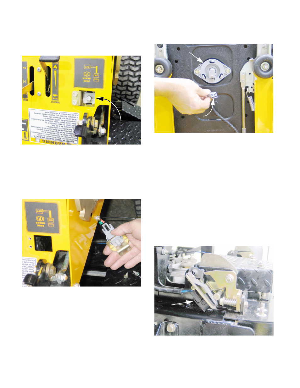
28.9. Brake safety switch: The brake safety switch is
mounted in the control console, immediately
behind the parking brake lever. See Figure 28.9.
28.10.The switch is most easily reached for service by
removing the two screws holding the switch
bracket to the control housing using a 5/16”
wrench. Once disconnected, the bracket and
switch can be lowered beneath the frame for
access, then unplugged. See Figure 28.10.
28.11. The brake switch contains two sets of contacts:
•
One set is normally open, breaking the starter
circuit when the brake is not applied (switch
plunger up).
•
One set is normally closed, as indicated by the
letters “N.C.” stamped on the spades. The N.C.
contacts are part of the engine kill safety circuit.
28.12.Seat safety switch: See Figure 28.12.
•
The switch is enclosed in a housing that
attaches into the bottom of the seat with two
screws. They can be removed using a 3/8”
wrench.
•
The contacts in the switch are normally closed
(N.C.).
•
The switch is part of the engine kill safety circuit.
•
The plug that connects to the switch contains a
contact that closes the circuit if the switch is
unplugged, defaulting to a closed circuit rather
than an open circuit.
28.13.Wing lift safety switch: The wing lift safety
switches are normally open (N.O.), and wired
together in series. See Figure 28.13.
Figure 28.9
Brake safety
switch
Figure 28.10
Figure 28.12
Seat safety switch
Seat safety switch plug
(defaults to closed circuit
when unplugged)
Figure 28.13
Wing lift
safety switch