Cub cadet commercial z-wing – Cub Cadet Z-Wing User Manual
Page 64
Cub Cadet Commercial Z-Wing
60
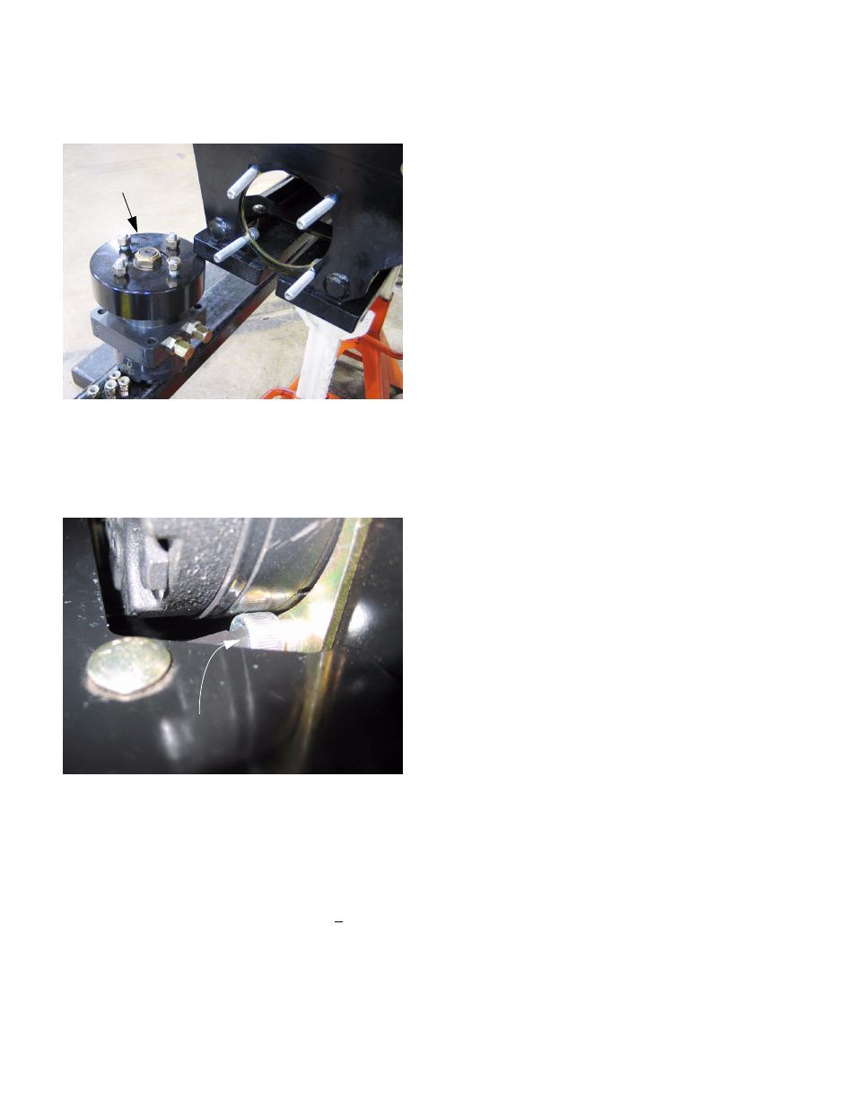
26.11. Reverse the removal process to install the wheel
motor. See Figure 26.11.
26.12.Access to the socket head cap screws around
the weights is tight. Once in position, a ball drive
allen wrench can be wedged against the weights
to ease installation. See Figure 26.12.
•
If the locking feature of the nut has worn, replace
the nut, or apply a small amount of thread lock-
ing compound such as Loctite 242 (blue) to the
threads. Tighten the nut to a torque of 80 ft-lbs
(108.48 Nm).
•
Tighten the lug nuts to a torque of 60 +10 ft-lbs
(68-95 Nm).
26.13.Re-fill the reservoir with Hydraulic Drive System
Fluid Plus.
26.14.Confirm that no hazardous condition will be cre-
ated by running the engine or operating the drive
system.
26.15.Open the relief valve of the pump that drives the
newly replaced wheel motor.
26.16.Start the engine and purge the drive system:
•
Give the lap bar ten strokes over the full distance
of it’s travel, taking about 10 seconds to com-
plete each stroke.
•
Turn off the engine. Check the fluid level and
top-up if necessary. Check for leaks. Close the
relief valve.
•
Start the engine.
•
Give the lap bar ten strokes over the full distance
of it’s travel, taking about 10 seconds to com-
plete each stroke.
•
Turn off the engine. Check the fluid level and
top-up if necessary. Check for leaks. Close the
relief valve.
•
Lower the rear of the mower to the ground.
26.17.Adjust tracking as necessary.
26.18.Test the operation of the mower and its safety
features in a safe area that is clear of hazards,
obstacles, and other personnel before returning
it to service. Some growling noise may come
from the drive system until all the air is purged.
Figure 26.11
Wheel motor
removed
Figure 26.12
Ball drive Allen wrench