Linkage neutral adjustment, Cub cadet commercial z-wing – Cub Cadet Z-Wing User Manual
Page 40
Cub Cadet Commercial Z-Wing
36
17.
LINKAGE NEUTRAL ADJUSTMENT
17.1. Preliminary steps:
•
Repair or replace any worn or damaged linkage
components before attempting to adjust the
steering linkage.
•
Confirm that the parking brake interlock is work-
ing properly-repair it if it is not.
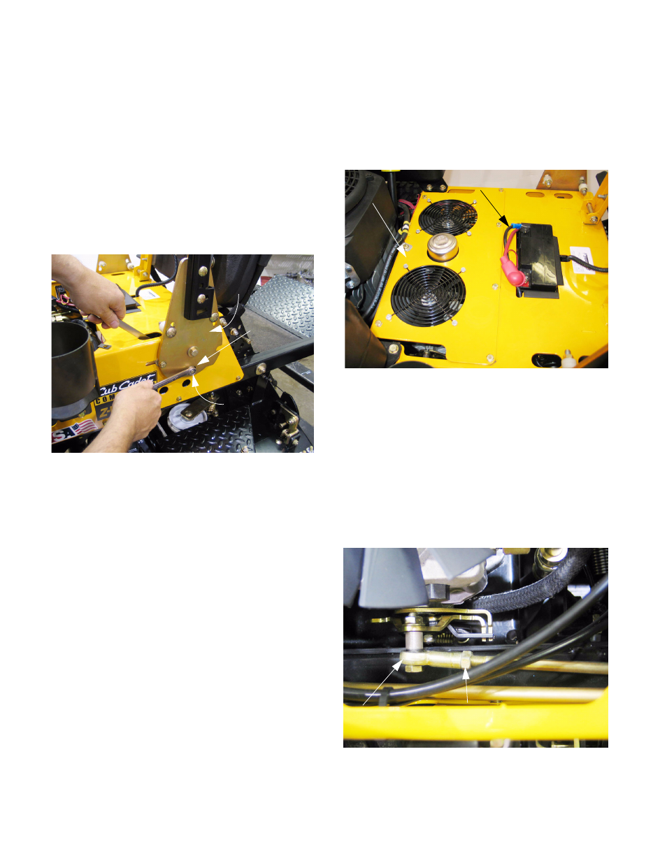
17.2. To isolate the problem to either the linkage or the
hydro pumps, loosen the nut and bolt that
secure the linkages to the steering pivot plates
using two 1/2” wrenches. See Figure 17.2.
17.3. Repeat the test of neutral adjustment, as
described in the CHECKING NEUTRAL
ADJUSTMENT section of this manual.
•
If the mower still creeps, or the drive system is
working against the brakes when it should be in
neutral, and the linkage is loose enough not to
interfere with the return to neutral action: the
adjustment must be made at the hydro.
•
After adjustment at the hydro, the linkage is still
likely to need adjustment.
•
If the mower does not creep, and the drive sys-
tem is not working against the brakes (as indi-
cated by a whining or groaning noise), then the
problem lies in the linkage.
17.4. If the problem lay in the connection between the
steering link rod and the steering pivot plate, the
simple act of loosening the connection and care-
fully re-tightening it with the parking brake
applied should correct the adjustment.
17.5. If the bolt that makes the connection between
the steering link rod and the steering pivot plate
is against the end of the slot in the plate, then
the steering link rod will need adjustment.
17.6. To reach the steering link rod adjustment point,
remove the hydro service plate: See Figure 17.6.
•
Disconnect the cable from the negative terminal
on the battery using a 10 mm wrench.
•
Remove the seven perimeter bolts from the
hydro service plate using a 7/16” wrench.
•
Carefully lift the plate off of the mower.
17.7. Loosen both jam nuts that lock the adjustment
on the steering link rod using a 1/2” wrench
(nuts) and a 7/16” wrench to hold the spherical
rod end. See Figure 17.7.
Figure 17.2
Steering
pivot plate
Slotted hole
Connection to
steering link rods
Figure 17.6
Hydro service
plate
Negative battery
cable and post
Figure 17.7
Jam nut, hydro end
of steering link rod
Spherical
rod end