Deck wing lift mechanism: early 2005 production, Deck wing lift mechanism:early 2005 production, Cub cadet commercial z-wing – Cub Cadet Z-Wing User Manual
Page 28
Cub Cadet Commercial Z-Wing
24
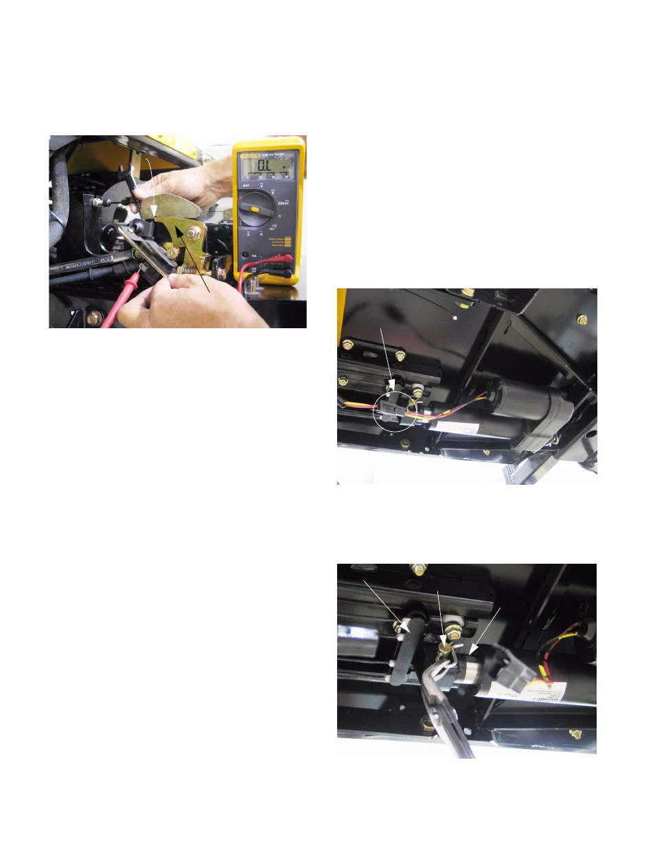
11.18. The switches are correctly adjusted when the
contacts break just as the corner of the hinge
lock clears the corner of the hinge.
See Figure 11.18.
11.19. Test the operation of the switches after service is
complete, but before the lift wing shields are
reinstalled.
12.
DECK WING LIFT MECHANISM:
EARLY 2005 PRODUCTION
NOTE: Decks having U-shaped front lift rods
were used on all Z-Wings produced after Nov. 1,
2005 (S/N: 0K015Z00001). These decks are ret-
rofittable to earlier production. Earlier decks are
easily identified by V-shaped front lift rods that
connect to the deck at a single point.
12.1. Refer to the electrical section of this manual for
electrical diagnosis of the wing lift actuator.
12.2. The cable cores are all nylon jacketed, and
should have long service lives.
•
Lubrication may be detrimental to the cables in
some operating conditions, adhering grit to the
cable or softening the cable core jacket.
•
If any lubricant is applied, use a dry product like
graphite or dry Teflon (PTFE) such as Tri-flo
brand.
12.3. If one cable needs replacement, and it has not
suffered from some identifiable damage or
cause for accelerated wear, a good case can be
made for replacing all four cables.
12.4. To remove the wing lift actuator, remove the cut-
ting deck as described in the CUTTING DECK
REMOVAL section of this manual.
12.5. Retract the actuator:
•
Insert the key in the key switch and turn it to ON.
•
Work the rocker switch to lift the deck wings (dis-
connected), retracting the ram on the actuator.
•
Turn the key switch OFF and remove the key.
•
If the actuator has failed in the fully extended
position, or if the cable bracket is to be removed,
follow the steps described later in this section.
12.6. Disconnect the electric plug joining the actuator
to the rest of the harness. See Figure 12.6.
12.7. Remove the hairpin clip and clevis pin and con-
necting the rear (ram) of the actuator to the
cable bracket. See Figure 12.7.
Figure 11.18
Corner of hinge
Hinge lock
Figure 12.6
Disconnect
Figure 12.7
Cable bracket
Clevis pin
Ram end of
actuator