Cub cadet commercial z-wing – Cub Cadet Z-Wing User Manual
Page 48
Cub Cadet Commercial Z-Wing
44
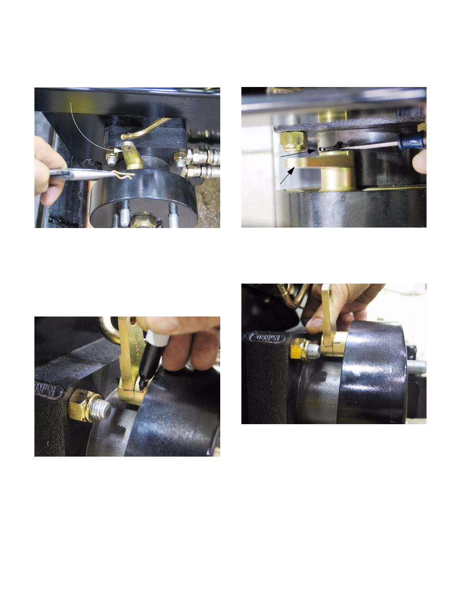
21.23.Remove the hairpin clip that secures the brake
rod to the brake arm. The brake return springs
will center the brake arm. See Figure 21.23.
21.24.Some idea of which way the arm needs to move
can be obtained by comparing the position of the
arm (now centered in the “OFF” position) to the
end of the brake rod that engages the arm.
21.25.Match-mark the initial position of the arm to pro-
vide a point of reference. See Figure 21.25.
21.26.Carefully pry-off the clip that holds the brake arm
onto the splined end of the brake cam shaft.
See Figure 21.26.
21.27.Rotate the brake arm one spline in the direction
that needed to bring the adjustment nut back
into its operating range. See Figure 21.27.
21.28.Re-connect the brake rod to the brake arm, and
adjust as necessary to make the brakes work
properly.
21.29.If further adjustments are needed to the arm
position, they can be made before the final nut
adjustments are made.
21.30.The final aspect of adjusting the brake linkage is
to make sure the interlock between the brake
and the steering pivot plates is working correctly.
Figure 21.23
Brake arm, to be adjusted
Figure 21.25
Figure 21.26
Spring clip
Brake arm
Figure 21.27