Electrical: starter circuit, Cub cadet commercial z-wing – Cub Cadet Z-Wing User Manual
Page 77
Cub Cadet Commercial Z-Wing
73
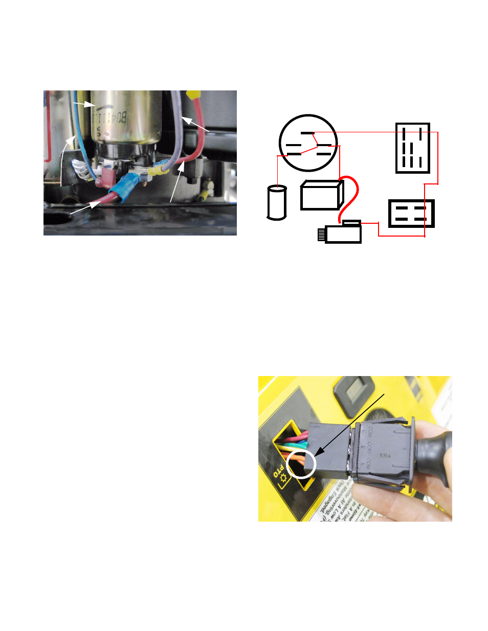
28.33.Engine harness - starter solenoid and starter:
The starter solenoid is attached to the starter
motor. See Figure 28.33.
•
The blue wire triggers the solenoid.
•
The violet wire carries charging current from the
regulator / rectifier.
•
The heavy gauge red cable carries battery cur-
rent to the starter and carries charging current to
the battery while the engine is running.
•
The smaller gauge red wire is not used in this
application.
Figure 28.33
Trigger wire:
Blue
Starter
solenoid
Charging
system
out-put:
Violet
Heavy gauge red cable
to + battery terminal
Unused fused line:
Red 12 ga.
29.
ELECTRICAL: STARTER CIRCUIT
29.1. With the key in the START position, terminals B,
S, and L are connected within the switch.
See Figure 29.1.
29.2. Terminal B is connected to the positive post of
the battery through a light gauge wire (red with
black trace) carrying a 20A in-line fuse.
29.3. The S terminal transfers battery power from the
B terminal to an orange wire with white trace (O/
w) when the key is in the START position.
29.4. The orange wire w/white trace leads to the com-
mon spade on the A set of contacts (A-COM)
within the PTO switch. See Figure 29.4.
•
When the PTO switch is turned-off, power goes
from A-COM to A-NC (orange w/ black trace).
•
When the PTO switch is on, the circuit is open.
Figure 29.1
S
M B
L G
Battery
A-F
Sol.
Starter
PTO Switch: OFF
Key Switch:
START
Brake Switch: ON
Figure 29.4
Orange wires =
Starter circuit