Cub cadet commercial z-wing – Cub Cadet Z-Wing User Manual
Page 73
Cub Cadet Commercial Z-Wing
69
28.14.The contacts in the switches are closed when
the plungers are depressed by lowering the
wings.
•
For adjustment procedures, refer to sub-sections
11.15 through 11.17 in the HINGE LOCK: LATE
2005 PRODUCTION section of this manual, or
sub-sections 9.15 and 9.16 in the DECK WING
AND HINGE LOCK section of this manual. Use
whichever instructions that apply to the mower
being serviced.
•
Remove the lift wing shield using a 9/16” wrench
to gain access to the switch.
28.15.Wing lift control switch: To remove the switch:
•
Remove the hydro service plate using a 3/8”
wrench.
•
Reach forward in the left side of the control
housing to disconnect and remove the wing lift
control switch.
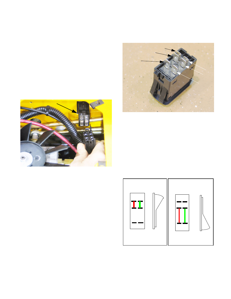
Figure 28.15
Wing lift control switch
28.16.There are six spade terminals on the back of the
deck wing lift control switch, oriented in two col-
umns of three: See Figure 28.16.
•
Spades in one column are numbered: 1, 2, & 4.
•
Spades in the second column are numbered: 5,
6, & 8.
•
The center spade in each column (#2 and #6)
are common, with #2 (red / black trace) carrying
power and #6 (black) carrying ground.
28.17.Rocking the switch in one direction closes con-
tacts joining #1 to #2 (yellow) and #5 to # 6 (red),
connecting power to terminal #2 and ground to
terminal #5. See Figure 28.17.
28.18.Rocking the switch in the opposite direction
closes contacts joining #2 to #4 (red) and #6 to
#8 (yellow), connecting power to terminal #4 and
ground to terminal #8.
Figure 28.16
1
2
5
6
8
4
Figure 28.17
1 5
2 6
4 8
1 5
2 6
4 8
DOWN UP