Cub cadet commercial z-wing – Cub Cadet Z-Wing User Manual
Page 19
Cub Cadet Commercial Z-Wing
15
9.6.
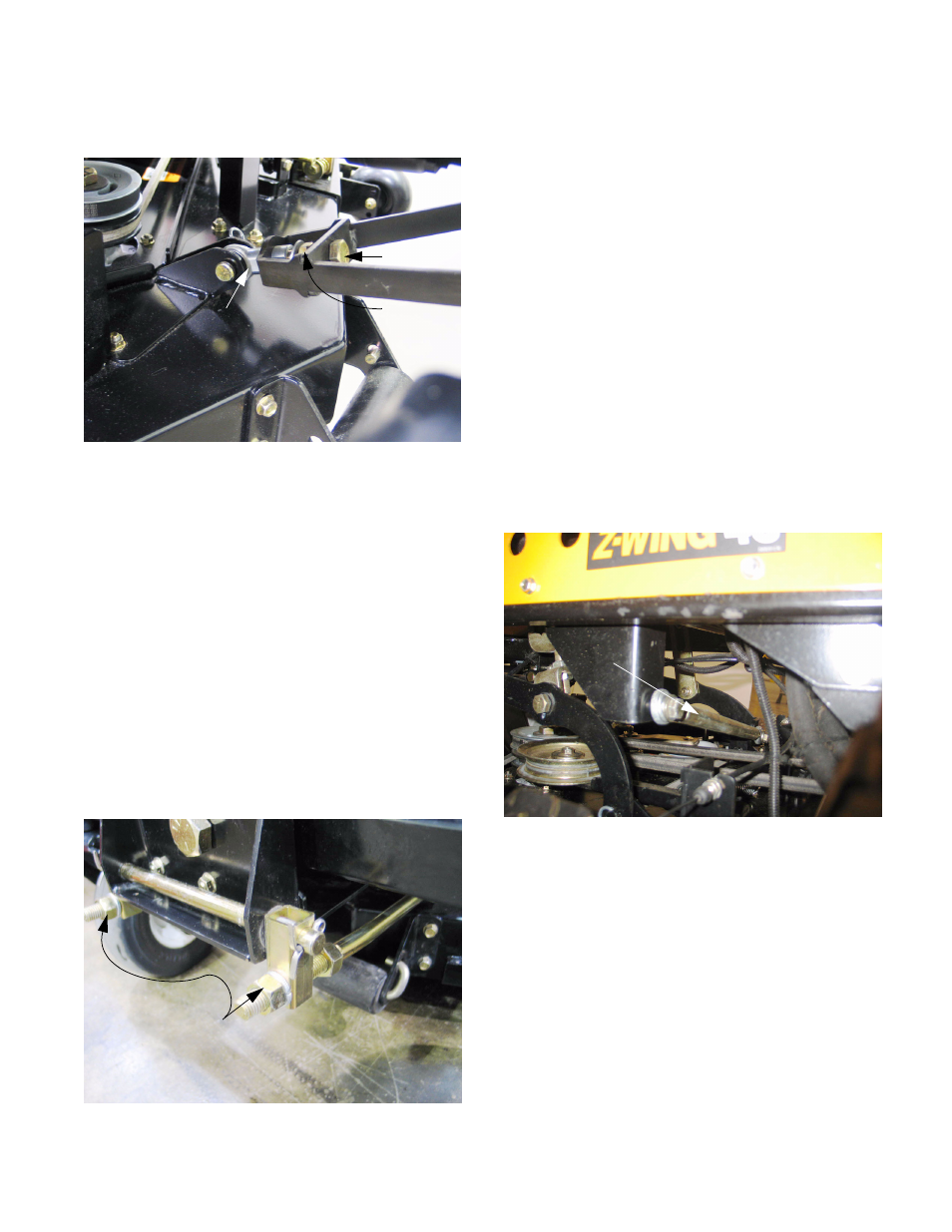
Deck pitch adjustment: Mowers produced
before November 2005. See Figure 9.6.
•
Loosen the jam nut that locks against the spheri-
cal rod-end connecting the front of the cutting
deck to the front lift arm assembly using a 15/16”
wrench.
•
Tighten or loosen the pitch adjustment bolt as
required to achieve a nose-down blade attitude
(lower at the front of the blade than at the back)
of 1/8” to 1/4” (3.175mm and 6.35mm) using a
15/16” wrench.
•
Secure the adjustment by tightening the jam nut.
9.7.
Run and test the mower, inspecting cut quality,
before returning the mower to service.
9.8.
Deck pitch adjustment: Mowers produced after
November 2005, or retrofitted with a new deck
after November 2005: See Figure 9.8.
Figure 9.6
Adjustment
bolt
Jam nut
Spherical rod end
Figure 9.8
U-shaped deck lift
bar has two adjustment points
•
Loosen the jam nuts that lock against the front
rod lift tube using a 15/16” wrench.
•
Tighten or loosen the pitch adjustment nuts as
required to achieve a nose-down blade attitude
(lower at the front of the blade than at the back)
of 1/8” to 1/4” (3.175mm and 6.35mm) using a
15/16” wrench.
•
Tension on the adjusting nuts should be even.
If it is not, the looser side will amplify deck vibra-
tions.
•
Secure the adjustment by tightening the jam nut.
•
The effect of adjustment is greater at lower cut-
ting heights because the front deck lift arm is
closer to horizontal at higher cutting levels. It is
important to make this adjustment at the level
used most frequently by the operator.
9.9.
Run and test the mower, inspecting cut quality,
before returning the mower to service.
9.10. Lateral brace adjustment: See Figure 9.10.
•
Mowers produced after mid-season 2005, but
before November of 2005 are equipped with a
lateral brace between the frame and the mowing
deck, similar to a panhard rod in the rear sus-
pension of a car or truck.
•
The lateral brace length should be adjusted so
that at the middle of the deck’s height travel it
exerts no force on the deck: if one of the mount-
ing bolts is removed it will slip back-in without
force.
Figure 9.10
Lateral
brace