Lap bars, Cub cadet commercial z-wing – Cub Cadet Z-Wing User Manual
Page 38
Cub Cadet Commercial Z-Wing
34
14.19.Assembly notes: See Figure 14.19.
•
Apply anti-seize compound to the friction sur-
faces where the lift shaft assembly rides on the
lift hubs and the lift links.
•
Use the shock cord technique to hold the
assembly together for installation.
•
Tighten the bolt to a torque of 20-25 ft-lbs (27-34
Nm). Apply a small amount of thread locking
compound such as Loctite 242 (blue).
•
A magnetic socket, or the gun patch technique
may be used to get the lift hub bolts started.
•
Install the cutting deck as described in the CUT-
TING DECK REMOVAL section of this manual.
•
If a lift hub should loosen, or the threads should
get stripped in the field, it is possible to reinforce
the installation with 3/8-16 nuts until a more per-
manent repair can be effected.
15.
LAP BARS
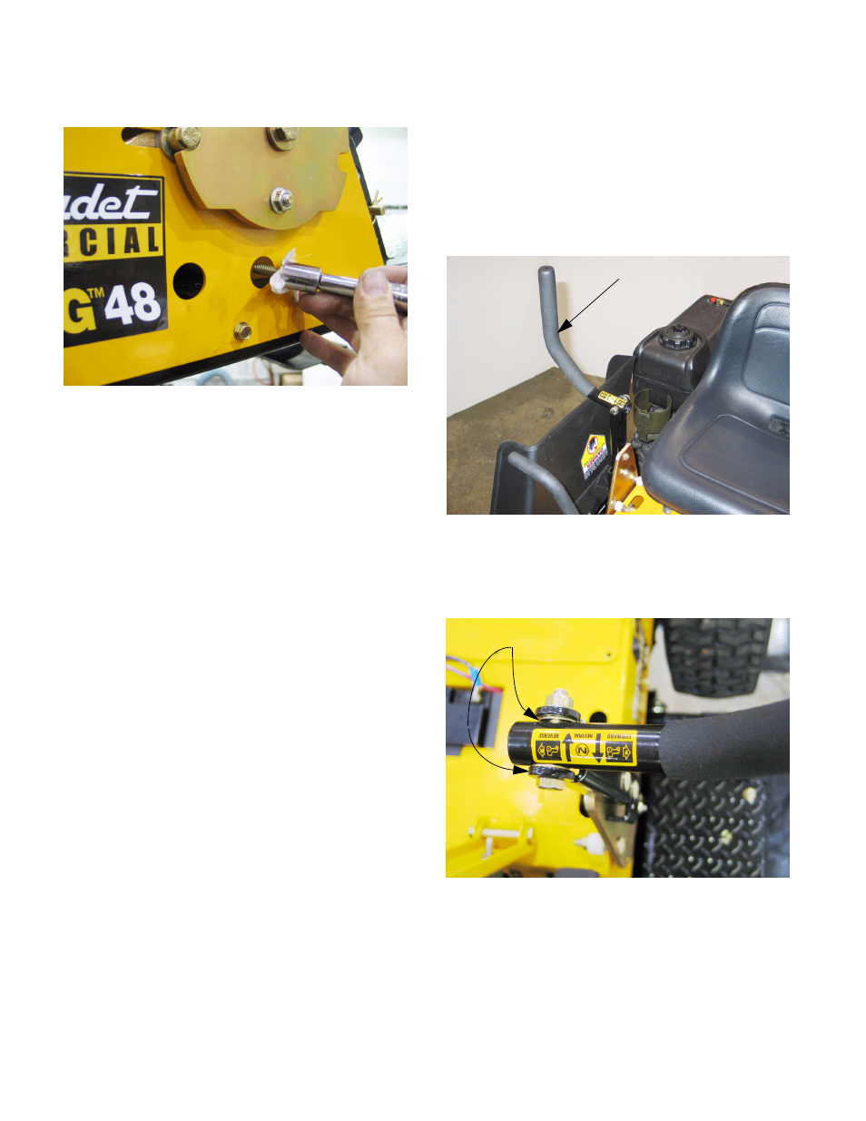
15.1. The lap bars do not have room to pivot outward
in the conventional manner because they would
interfere with the deck wings in the raised posi-
tion. For this reason, separate pivot handles
articulate on the lap bar pivot brackets which
fasten to the steering pivot plate.
See Figure 15.1.
15.2. The pivot handles are bolted to the lap bar pivot
brackets, with washer on each side of the pivot
bar handle. See Figure 15.2.
•
The bolts should be tight enough to eliminate
play, but loose enough that they do not bind.
•
Periodic tightening may be necessary using two
9/16” wrenches.
•
Lubricate the joints weekly, per the Operator’s
Manual.
Figure 14.19
Figure 15.1
Pivot handle
Figure 15.2
Washers