Hinge lock: late 2005 production, Cub cadet commercial z-wing – Cub Cadet Z-Wing User Manual
Page 24
Cub Cadet Commercial Z-Wing
20
11.
HINGE LOCK: LATE 2005 PRODUCTION
11.1. When the wing lift is activated, all four cables,
hinge locks, and lift mechanisms should work in
unison: See Figure 11.1.
•
The force applied through the cable rotates the
cable bracket inward.
•
The socket head cap screw attached to the
cable bracket moves upward, releasing the
plunger on the safety switch and rotating the
hinge lock clear of the corner of the deck hinge
•
The force of a compression spring keeps the
hinge lock applied when the cable is slack.
•
When the spring is compressed and the hinge
lock is clear of the hinge, the cable will begin to
lift the deck wing.
•
A clutch within the actuator prevents over-travel
when the wings reach the fully raised position.
•
The safety switches prevent the operation of the
PTO with the deck wings raised.
•
Proper adjustment is very important: refer to the
DECK WING CABLE ADJUSTMENT section of
this manual for the correct procedure.
•
Proper hinge alignment is very important. If a
hinge becomes bent or damaged, it must be
repaired before the mower is used.
11.2. The revised hinge lock (2005/2) differs from the
original hinge lock (2005/1) in the following
ways:
•
There is greater range of motion between the
point that the socket head cap screw releases
the plunger on the safety switch and the point
that it contacts the hinge lock.
•
There is a torsion spring connecting the hinge to
the cable bracket, giving the cable bracket more
positive return action.
•
A J-nut has been positioned in a notch on the
hinge. The J-nut is hardened. This provides a
hard flat surface for the hinge lock to operate
against. The wear resistance of the J-nut will
provide more consistent locking action over
time, and is easily replaced.
•
The compression spring that engages the hinge
lock is mounted on shouldered socket head cap
screw, eliminating the possibility of misadjust-
ment.
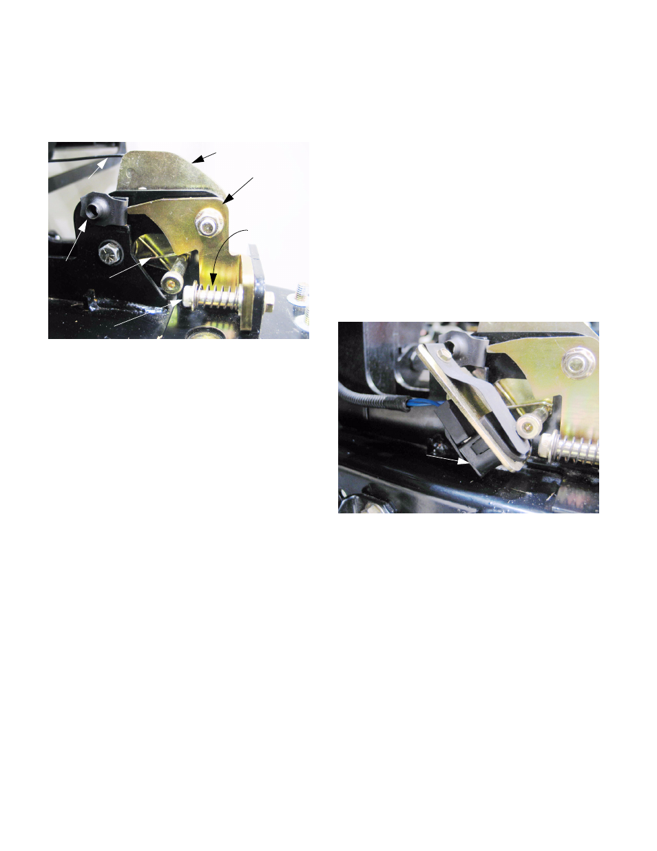
11.3. The Safety switch that is mounted to each rear
hinge lock prevents the electric PTO from
engaging when the wings are not latched in the
down position. See Figure 11.3.
Figure 11.1
Cable
Cable bracket
Hinge lock
NOTE:
new profile
J-nut
Torsion spring
Shouldered
cap screw
Compression
spring
Figure 11.3
Safety switch on
each rear hinge lock