Figure 3-9, To the crossed o, Wn in – Cabletron Systems 2M46-04R User Manual
Page 36
Chapter 3: Installation
3-12
2M46-04R/2M46-04RDC User’s Guide
Figure 3-9
FE-100TX Crossover Switch
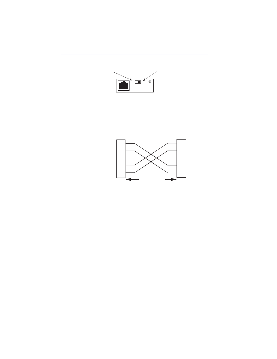
A schematic of a crossover cable is shown in
Figure 3-10
Schematic of Crossover Cable
Connect an FE-100TX to a twisted pair segment as follows:
1.
Ensure that the device connected to the other end of the segment is
powered ON.
2.
Connect the twisted pair segment to the module by inserting the RJ45
connector on the twisted pair segment into the RJ45 port on the
module shown in
3.
Verify that a link exists by checking that the port RX LED is ON
(flashing amber, blinking green, or solid green). If the RX LED is OFF
and the TX LED is not blinking amber, perform the following steps
until it is on:
a.
Verify that the 100BASE-TX device at the other end of the twisted
pair segment is powered up.
Position X
(crossed over)
1. RX+
2. RX-
3. TX+
4. NC
5. NC
6. TX-
7. NC
8. NC
Position =
(not crossed over)
1. TX+
2. TX-
3. RX+
4. NC
5. NC
6. RX-
7. NC
8. NC
FE-100TX
10
16651_05
100
=
x
TX+
TX–
RX+
RX–
2
1
3
6
TO
10BASE-T Device Port
TX+
TX–
2
1
3
6
NOTE:
RX+/RX– and TX+/TX–
must share a common
color pair.
TO
RJ45 Port
2251-31
RJ45 to RJ45
RX+
RX–