5 test menu – Rice Lake Static Weighing User Manual
Page 37
Configuration
33
3.5
Test Menu
A/D
DIG I/O
COMM
KEYPAD
RAM
RAW
ZERO
SPAN
mV
VAL
VAL
VAL
VAL
LOOP
DIO 1
DIO 2
DIO 3
STATUS
DIO 4
STATUS
STATUS
STATUS
PORT1
PORT2
TEST
EXCVDC
VAL
WARNING...
DISCONNECT
DIGITAL I/O
BEFORE
RUNNING TEST
PASS
or
FAIL
PASS
or
FAIL
PASS
or
FAIL
PASS
or
FAIL
EXIT
T&D
TEST
SETUP
AUDIT
XXXXXXX
CALIBR
BRIGHT
ACCUM
Only displayed if
turned on
from Setup menu
ID
Only displayed if
turned on
from Setup menu
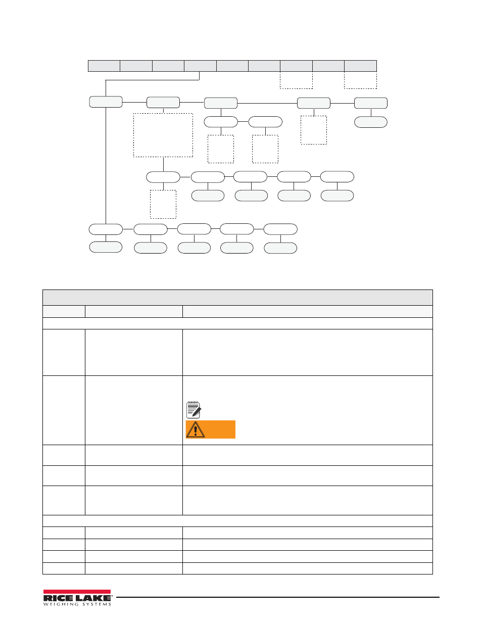
Figure 3-11. Test Menu
TEST Menu
Parameter
Choices
Description
Level 2 submenus
A/D
RAW
ZERO
SPAN
mV
EXCVDC
Gives details of current or live A/D counts as well as stored zero and span A/D
values.
Shows voltage levels for signal and excitation voltages.
DIG I/O
LOOP
DIO 1
DIO 2
DIO 3
DIO 4
Tests your digital I/O ports. If they are functioning, “PASS” is displayed. If they are
not functioning, “FAIL” is displayed.
WARNING
Note
Both inputs and outputs are active low. They go to a ground
state when active.
The I/O ports become activated when the test is
performed. Ensure all equipment is disconnected prior to
performing this test to avoid it being activated.
COMM
PORT1
PORT2
Performs a loopback test on the serial ports. If they are functioning, “PASS” is
displayed. If they are not functioning, “FAIL” is displayed.
RAM
TEST
Tests the unit’s memory. if it is functioning, “PASS” is displayed. If it is not
functioning, “FAIL” is displayed.
KEYPAD
TEST
Tests the unit’s individual keypad buttons by displaying the name of the key
pressed. If nothing is displayed, the key is not functioning.
Press the Menu key to exit the test.
Level 3 submenus
RAW
VAL
Displays the live current raw A/D count.
ZERO
VAL
Displays the captured A/D Zero calibration value.
SPAN
VAL
Displays the captured A/D Span calibration value.
mV
VAL
Displays the live current millivolt signal voltage.
Table 3-8. TEST Menu Parameters