7 cable grounding, 1 serial communications, Serial communications – Rice Lake Static Weighing User Manual
Page 12
8
CW-90/90X Checkweigher
2.7
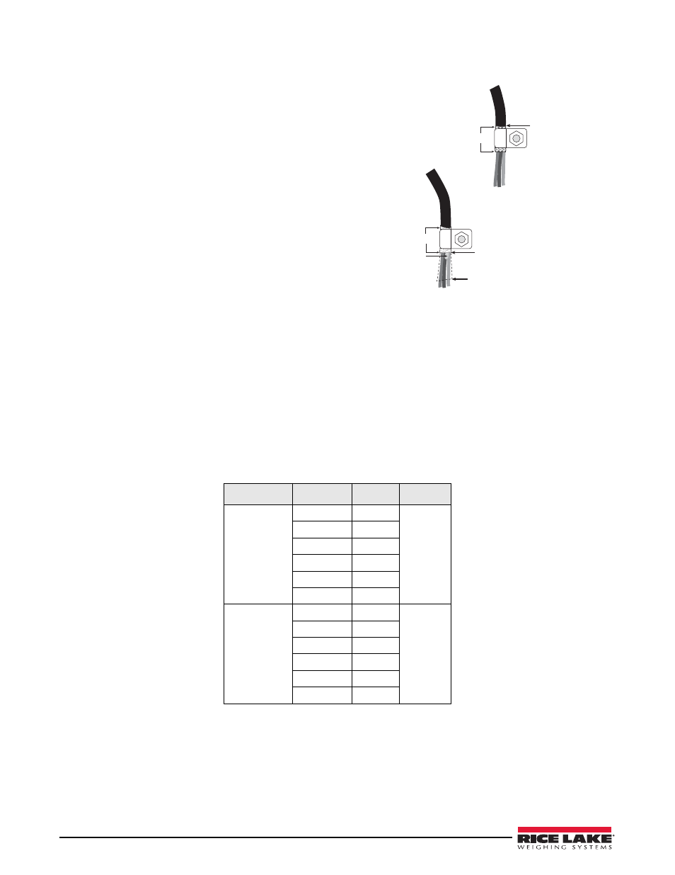
Cable Grounding
Except for the power cord, all cables routed through the
cord grips should be grounded against the indicator
enclosure. Do the following to ground shielded cables.
Insulated cable
Foil (silver side out)
Grounding clamp
Shield wire (cut)
Length of foil before folding
back on cable insulation
Cut insulation here
for foil-shielded cables
Braid
Cut insulation here
for braided cables
NOTE: Install lockwashers
first, against backplate,
under grounding clamp
Figure 2-3. Grounding Clamp Attachment for
Foil-Shielded and Braided Cabling
•
Use the lockwashers, clamps, and kep nuts
provided in the parts kit to install grounding
clamps on the enclosure studs adjacent to cord
grips. Install grounding clamps only for cord
grips that will be used; do not tighten nuts.
•
Route cables through cord grips and grounding
clamps to determine cable lengths required to
reach cable connectors. Mark cables to remove
insulation and shield as described below:
•
For cables with foil shielding, strip insulation and
foil from the cable half an inch (15 mm) past the
grounding clamp (see Figure 2-3). Fold the foil
shield back on the cable where the cable passes
through the clamp. Ensure silver (conductive)
side of foil is turned outward for contact with the
grounding clamp.
•
For cables with braided shielding, strip cable
insulation and braided shield from a point just past the grounding clamp. Strip another half inch (15 mm)
of insulation only to expose the braid where the cable passes through the clamp (see Figure • on page 8).
•
Finish installation using cable mounts and ties to secure cables inside of indicator enclosure.
2.7.1
Serial Communications
Wire the serial communications cables to J2, which is Port 1 (5-wire RS-232 port). J3 is Port 2 (RS-232 and 20
mA). Connect communications cables to J2 and J3 as shown in Table 2-3.
Use cable ties to secure serial cables to the inside of the enclosure.
Port 1 supports full duplex RS-232 communications only; Port 2 provides either active 20 mA output or duplex
RS-232 transmission. Both ports are configured using the SERIAL menu. See Section 3.4.4 on page 29.
Connector
Pin
Signal
Port
J2
1
Ground
1
2
Ground
3
Tx
4
Rx
5
DTR
6
RTS
J3
1
20mA+
2
2
Ground
3
Tx
4
Rx
5
CTS
6
RTS
Table 2-3. J2 and J3 pin assignments