Cte-5100 series thermostat reference, Checkout and calibration – KMC Controls CSP-5002 User Manual
Page 7
CSP-5001/5002 VAV Flow Controller-Actuators
7
Applications Guide, Rev. B
CTE-5100 Series Thermostat Reference
Checkout and Calibration
The thermostat (CTE-5100 series) operates on a 16
volt DC power supply from the CSP controller and
outputs a 0–10 volt DC signal on the T(x) terminals
(Direct Acting T1 and Reverse Acting T2). See the
CTE-5100 Series Thermostat Reference Page for de-
tails on which ‘T’ terminals are used on each model
thermostat, but generally T1 and T3 are used for the
cooling mode and T2 and T4 for heating. T1 and T2
are adjustable to limit minimum and maximum flow.
T3 and T4 have a fixed 0–10 volt DC output signal
(over the proportional band).
NOTE: Limits may be set at the CSP or the CTE
thermostat. If setting the min/max limits
at the CTE thermostat, the CSP’s Min. dial
must be set fully CCW to 0 and the Max.
dial set fully CW to 100. This will ensure
that the CSP will not have any effect on the
limits.
1. Required tools:
• 1/16-inch hex/key wrench
• Small flat blade (1/8-inch) screwdriver
• Digital voltmeter capable of displaying a
0–10 volt DC range which will display in
hundredths of a volt.
• HSO-5001 test leads (optional for meter taps)
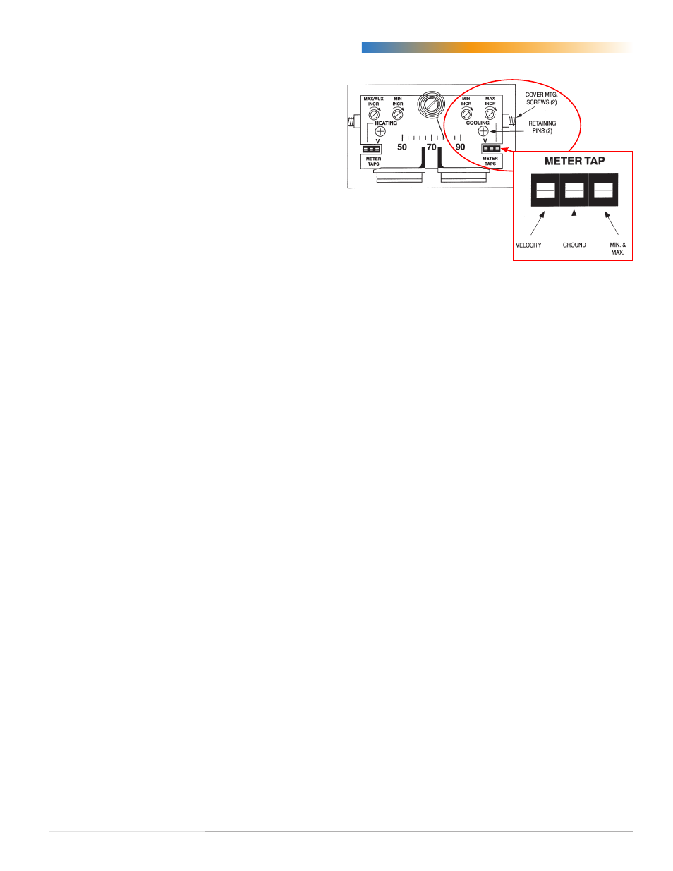
2. Remove the thermostat cover by loosening the
setscrews on each side of the thermostat (see
illustration). Using a 1/16-inch hex key wrench,
turn the setscrews clockwise until the cover is
loose.
3. Check voltages:
A. Verify 16 volts DC between (+) and (–)
terminals.
B. Measure “T(x)” to “–” for output voltage. Use
the calibration procedures below to adjust
limits if desired. Adjust the setpoint above and
below current room temperature and observe
changes in appropriate “T” voltage. Remove
setpoint slider stops (HFO-0027) if necessary.
NOTE: Always adjust minimum flow limits first.
4. Maximum limits will always be greater than
minimum limits. (Maximum is additive to
minimum.) If in doubt, turn maximum limit fully
clockwise (increase) before proceeding.
NOTE: Dials rotate approximately 200° (8:00
to 4:00). Turn clockwise to increase or
counterclockwise to decrease. Do not use
excessive force on dials. They should turn
freely and effortlessly. DO NOT force dial
beyond a stop.
5. Connect voltmeter to the meter taps (using the
HSO-5001 test leads adapter makes this easier).
A. Connect to the middle and right terminal (see
illustration) for the minimum and maximum
reading.
B. Connect to the middle and left terminal
for measuring actual flow velocity. (The
thermostat must be wired to a controller for
this option; see the Applications sections).
6. Adjust the minimum flow.
A. Push the cooling setpoint slider all the way to
the right. (This requests minimum flow, and
is normally for heating mode or cooling is
satisfied.)
B. Set the minimum flow voltage as desired
using the Min. dial (on the Cooling side of
thermostat).
7. Adjust the maximum flow.
A. Push the cooling setpoint slider all the way to
the left. (This requests maximum flow, and is
normally for full cooling mode.)
B. Set the maximum flow voltage as desired
using the Max. dial (on the Cooling side of the
thermostat).
8. Adjust the cooling setpoint slider back to its
original position and replace the cover.
NOTE: For use with the CTE-5202 thermostat
instead of the CTE-5100 series, see the
.