KMC Controls CSP-5002 User Manual
Page 16
CSP-5001/5002 VAV Flow Controller-Actuators
16
Applications Guide, Rev. B
CSP5001
Controller-Actuator
H
~
16
V
DC
I
N
O
U
T
L
24 VAC
REE5001 Relay Module
~
24
V
A
C
3
2
1
Stages
3-Stage Reheat
T
Load
(To Flow Sensor)
24 VAC @ 34 VA
~
12
V
V1 T3 R1 T1
A
+
CTE5103
T2 R2 T4 V2
REE1005 Relay Module
Y
X
Controller
5
4
A
NC
N
O
C
Sensor
24 VAC Contactors
(10 VA Max. per Stage)
TTE2001
Duct Sensor
1
2
3
2
1
3
Jumpers
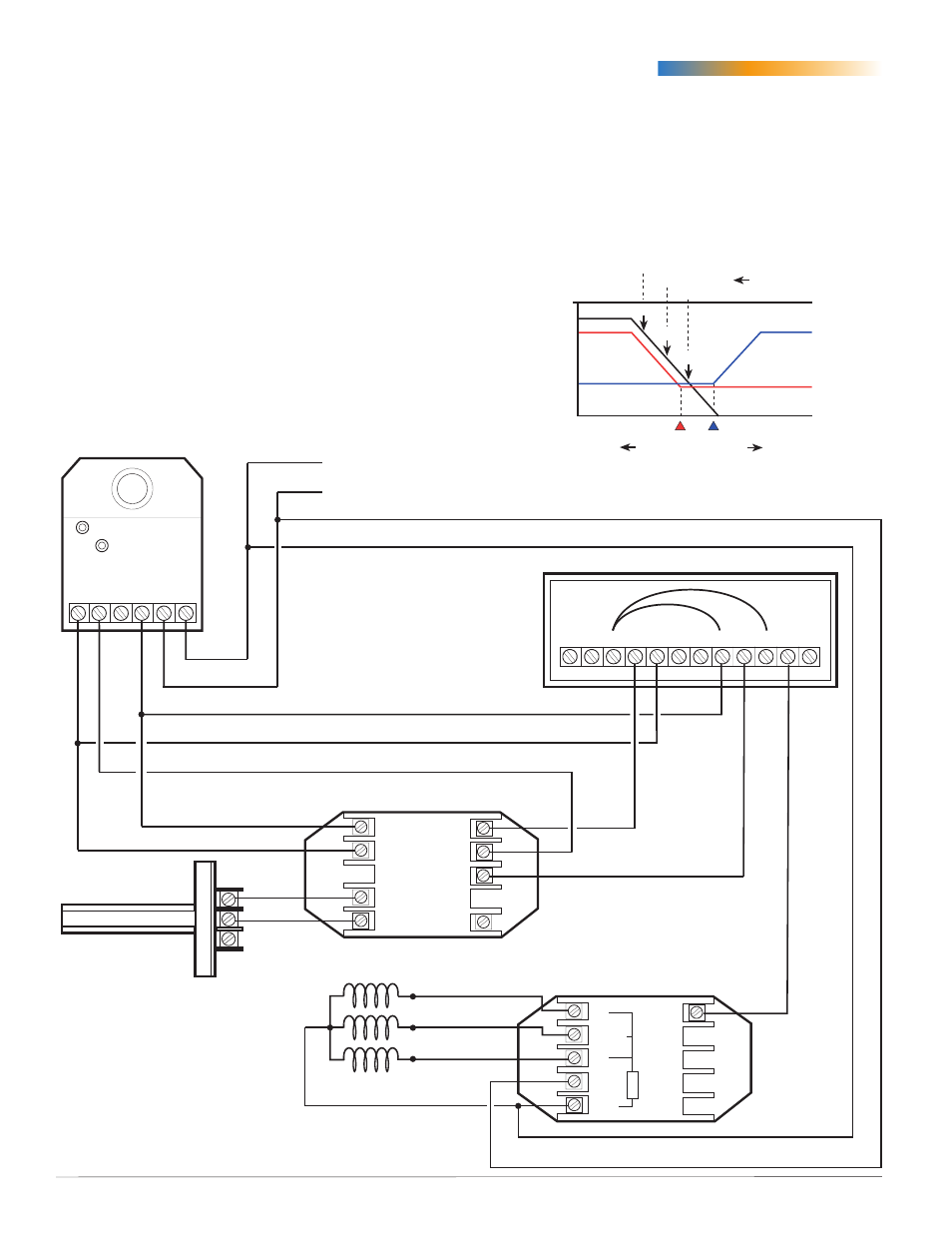
Cooling with Heating Changeover and Electric Reheat
NOTE: Minimums must be sufficient for reheat.
This application utilizes the same controls as Cooling
with Heating Changeover but adds the REE-5001
relay for electric reheat. When the VAV inlet air
temperature becomes warm (such as morning warm-
up), changeover occurs. In this mode, “T2” controls
the CSP-5001. The first stage of heat is enabled when
the space temperature is slightly above the heating
setpoint (3.5 volts). If the temperature continues to
drop, the second stage of heat comes on, followed
by the third stage. See the chart for reference of each
heat stage activation.
Heating
Max.
Heating Min.
0 fpm
(
Colder
Room Temperature
Warmer
)
3300
fpm
T2
Signal
Cooling
Max.
Cooling Min.
T1
Signal
Cooling Setpoint
Heating Setpoint
Air
Flow
9.5 V
6.5 V
3.5 V
#3
#2
#1
Reheat
Stages
T4 Signal
T4 Voltage
NOTE: REE-1005 terminal “A” can be used to
trigger an auxiliary flow setpoint when
used with a CTE-5104 or REE-1012. This
terminal can also be used to daisy chain
more than one REE-1005 together by wiring
Terminal “A” to Terminal “Y” on the next
relay.
(Former Ref. # APE-1-50014A)