Cooling with 3-stage reheat – KMC Controls CSP-5002 User Manual
Page 13
CSP-5001/5002 VAV Flow Controller-Actuators
13
Applications Guide, Rev. B
CSP5001
Controller-Actuator
H
~
16
V
DC
I
N
O
U
T
L
24 VAC
REE5001 Relay Module
~
24
V
A
C
3
2
1
Stages
3-Stage Reheat
T
Load
(To Flow Sensor)
24 VAC @ 34 VA
~
24 VAC Contactors
(10 VA Max. per Stage)
2
1
3
12
V
V1 T3 R1 T1
A
+
CTE5104 Thermostat
T2 R2
Jumper
for
Automatic
Auxiliary
Flow for
Heating
Jumper
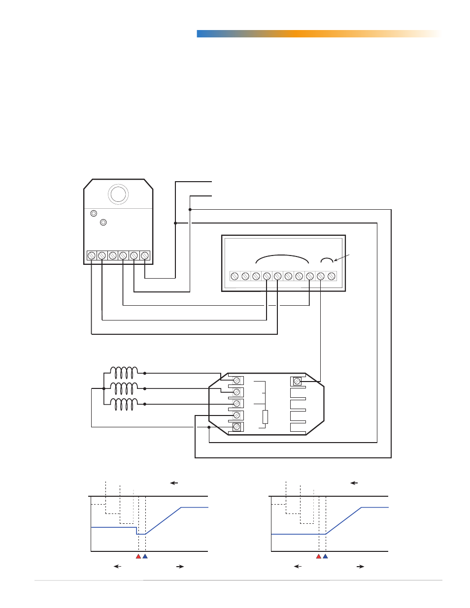
Cooling with 3-Stage Reheat
The CTE-5104 electronic thermostat is a dual-
setpoint thermostat for heating (RA) and cooling
(DA) applications. The application below uses an
REE-5001 relay module and three 24 VAC contactors
for three stages of reheat.
The diagram below shows a jumper between “T2”
and terminal “R2” on the thermostat to permit
auxiliary flow. As the temperature drops below
setpoint, the first stage of reheat begins. As the
temperature continues to drop, the second stage
begins and so on (see the first chart). This auxiliary
flow is used as a second minimum flow before
enabling the reheat stages.
When the auxiliary flow is not being used (see the
second chart), connect the jumper between terminals
“R2” and “–” and turn the auxiliary dial fully CCW
to ensure it will have no effect.
Air
Flow
0 fpm
Reheat Setpoint
(
Colder
Room Temperature
Warmer
)
3300
fpm
Cooling
Max.
Cooling Setpoint
T1
Signal
7.5 V
4.5 V
1.5 V
0 V
T2 Voltage
#3
#2
#1
Reheat Stages
Cooling Min.
Aux. Setting
Air
Flow
0 fpm
Reheat Setpoint
(
Colder
Room Temperature
Warmer
)
3300
fpm
Cooling
Max.
Cooling Setpoint
T1
Signal
7.5 V
4.5 V
1.5 V
0 V
T2 Voltage
#3
#2
#1
Reheat Stages
Cooling Min.
(Former Ref. # APE-1-5012)