Setback/setup resistor value – KMC Controls CSP-5002 User Manual
Page 14
CSP-5001/5002 VAV Flow Controller-Actuators
14
Applications Guide, Rev. B
CSP-5001
Controller-Actuator
H
~
16
V
DC
I
N
O
U
T
L
24 VAC
REE-5001 Relay Module
~
24
V
A
C
3
2
1
Stages
3-Stage Reheat
T
Load
(To Flow Sensor)
24 VAC @ 34 VA
~
24 VAC Contactors
(10 VA Max. per Stage)
2
1
3
12
V
V1 T3 R1 T1
A
+
CTE-5104 Thermostat
T2 R2
Jumper
for
Automatic
Auxiliary
Flow for
Heating
Jumper
SPST
Relay
Resistor
(see chart)
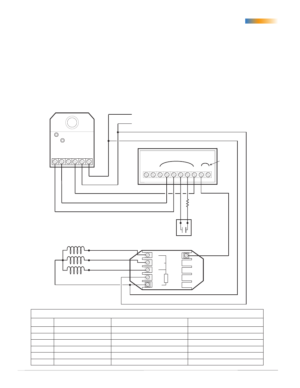
Cooling with 3-Stage Reheat and 10 Degree Night Setback/Setup
This configuration is the same as on the previous
page except for the simple addition of a SPST relay
or switch and a resistor (see chart below for value).
The switch or relay is driven by a night setback/
setup signal from other equipment not shown. When
the contact is closed (e.g., by a timer), the added
fixed resistance of, for example, 41.2K ohms between
thermostat terminals A and 12V would indicate
that the room is approximately 10° F warmer than
it really is. This would inhibit the heat stages from
coming on during the unoccupied mode (night
setback). If the resistor and switch are instead
connected between thermostat terminals A and –,
the room would seem 10° cooler than it really is,
inhibiting cooling during unoccupied times.
NOTE: This configuration requires the system fan
to be on during setback/setup mode.
Setback/Setup Resistor Value
Offset
Resistor Ohms (Ideal)
Common 1% Resistor Values
Common 5% Resistor Values
3° F
140.5K
147K
150K
5° F
84.129K
86.6K
82K
8° F
51.23K
52.3K
51K
10° F
40.483K
41.2K
39K
15° F
25.996K
26.1K
27K
20° F
18.267K
18.2K
18K