Rs-232 interface setup and test – Elecraft KPA100 Manual User Manual
Page 60
60
RS-232 Interface Setup and Test
Connect the KPA100 to the K2 Control board via the ribbon cable
(see page 25). Also connect the KPA100 speaker cable (J5) to the K2 RF
board.
Connect a low-current power supply to the K2's DC power input jack
(lower rear panel).
Turn on the K2.
Tap MENU and locate the ST L (sidetone volume) menu entry,
then hold
E D I T
to edit the parameter. If no sidetone is heard (due to the
Control board modification), tap DISPLAY to change the sidetone
source to U8-4 (default is U6-25). If you still don't hear the sidetone,
refer to Troubleshooting. Tap MENU twice to return to the frequency
display.
Turn off the K2.
KPA100 to Computer Cable Assembly
i
CAUTION: Do not use a pre-assembled cable of any kind
(printer cable, etc.) between the KPA100 and a computer. Some of
J8's pins provide special signals not intended for use with an RS-232
interface, and you could damage the K2, KPA100, or the computer if
these lines are used incorrectly.
Locate the 4-conductor cable. The cable can be cut to a shorter length
if desired, but it will work equally well at its full length (10', 3 m).
Remove 1/2" (12 mm) of the jacket from the cable. Be very careful
not to nick the individual wires.
Peel back and cut away the foil shield.
The white wire will not be used for serial communications, but
should be saved as a spare. Fold it against the cable jacket and secure it
with tape.
Strip off 3/16" (5 mm) of insulation from each insulated wire.
Twist the strands of each wire together and tin them lightly with
solder.
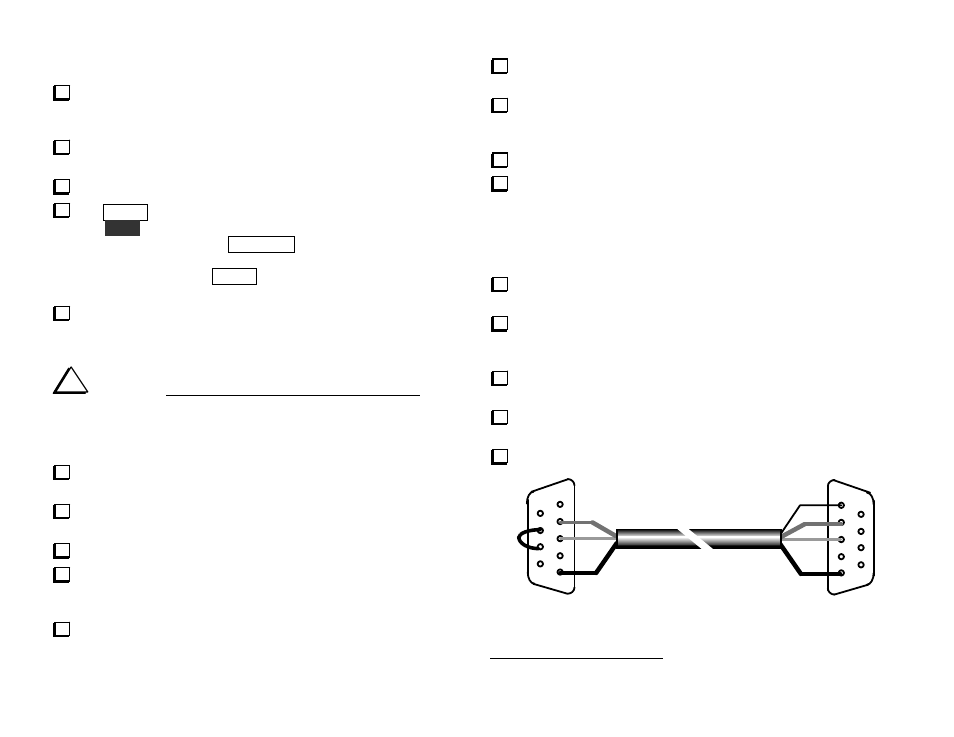
Locate the DB9F (female) and DB9M (male) connectors. Arrange
them as shown in Figure 42 (male connector on the right, solder cups
facing up). Make sure the 5-pin rows are facing each other.
Clamp the DB9F (female) connector into a padded vise, if available.
As shown in Figure 42, pins 7 and 8 of the female connector can be
wired together (using a discarded component lead) to provide RTS/CTS
loop-back
2
. Some software requires this hardware handshaking. We
recommend that you make this connection, unless you're sure that your
application software does not need it. Some programs use these lines for
CW keying, etc.
Clip the bare shield wire off at the PC end of the cable only. The
shield wire will be connected at the K2 end.
Solder the RED, GREEN, and BLACK wires of the PC end of the
cable (the end with no shield wire) to the female connector. Refer to
Figure 42.
Remove the female connector from the vise, and insert the male
connector. Keep this connector in the orientation shown.
Solder the BARE (shield), RED, GREEN, and BLACK wires to the
male connector as shown.
Remove the male connector from the vise.
K2 END
(MALE)
PC END
(FEMALE)
1
1
2
3
4
5
2
3
4
5
BARE
BLK
BLK
RED
RED
GRN
GRN
*
*
RTS/CTS LOOPBACK (SEE TEXT)
Figure 42
2
RTS = Request to send, CTS = Clear to send.