Remote control using the rs-232 port, Control board preparation – Elecraft KPA100 Manual User Manual
Page 59
59
Remote Control using the RS-232 Port
Control Board Preparation
If your K2 serial number is 3000 or higher, or if you have previously
installed a KIO2 option in your K2, skip the steps on this page and
continue with RS-232 Interface Setup and Test on page 60.
Turn off the K2. Before handling the Control board in the
following steps, touch a grounded surface.
Remove the screws that hold the K2 Control board to the front panel
board. Also remove the audio filter module if present.
Use the long-handled Allen wrench supplied with the K2 to pry the
Control board up at the point marked "LIFT HERE" on the RF board.
Place the Control board in front of you, component side up.
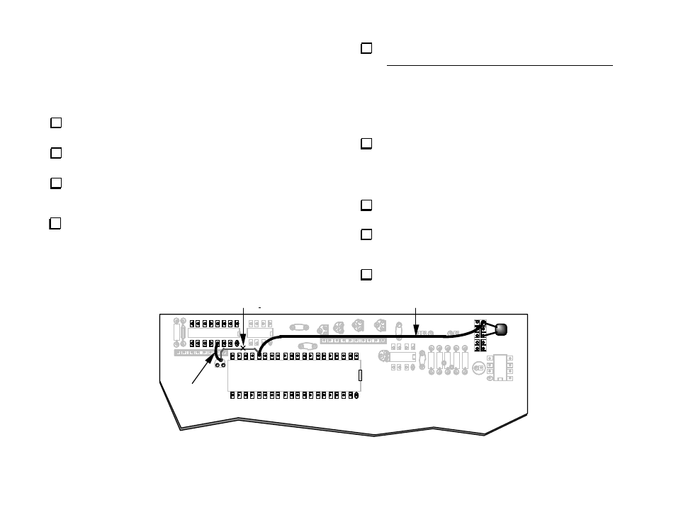
Figure 41 shows the bottom side of the Control board, where most of
the changes will be made. One trace will be cut on the top side.
The trace between Q5-gate and U6 pin 25 must be cut as shown
below. This trace is located on the top side of the Control board. Once
you have located the trace, use a sharp tool such as an X-acto knife to
make two small cuts near the location marked with an "X". Press down
with the tip--don't draw the knife across the trace, since you may slip,
cutting adjacent pads or traces. Next, pry up and remove the small
segment between the cuts. Examine the trace closely to make sure the cut
segment is completely removed.
Cut a 3/4" (19 mm) length of the supplied green-insulated hookup
wire, and remove 1/8" (3 mm) of insulation from each end. Install and
solder this jumper on the bottom of the board, between Q5-gate and U8
pin 4, as shown below. Make sure the jumper doesn't contact adjacent
pads or component pins.
Solder a .001 µF, 0.2" LS capacitor ("102") across P4, pins 1 and 5.
(Listed as Ctxd in the parts list.)
Prepare a 4" (10 cm) jumper using hookup wire. Solder it between
U6 pin 25 and P4 pin 1 on the bottom side of the board (pin 1 is the round
pad). Make sure the jumper doesn't touch adjacent pins.
Re-install the Control board (and KAF2 if applicable)
U6
U8
40
25
P4
Q5
1
1
Cut trace on top side
Jumper, 4"
Jumper, 3/4"
(to pin 4 of U8,
not to RP7)
.001 µF
B ottom view of Control b oard
Figure 41